


On this page
Choosing between single row vs double row LED light bars requires more than counting LEDs: compare the actual beam distribution, installed clearance, stabilized output and electrical demand of the specific products. A slim bar can be the better choice in a restricted opening; a taller bar can offer useful output when its optics, supply circuit and mounting location support the intended job.
This buying guide treats row count as a packaging characteristic. It helps you decide which information to collect before spending money, how to separate a meaningful specification from a decorative number, and how to evaluate a light after installation. The worked calculations below are hypothetical examples, not SAEC product measurements or promises of fitment. Current compatibility, installation instructions and operating limits must come from the exact light, harness, bracket and vehicle documentation.
What a single row or double row actually describes
A single-row light bar normally presents one horizontal line of LED optical positions across its face. A double-row bar normally presents two. That description tells you something about the visible layout, but it does not identify the LED package, reflector shape, lens design, drive current or usable beam. Two products with the same row count can differ substantially in every one of those characteristics. The term is a convenient way to sort packaging, not a standardized performance grade.
Even the word LED needs careful interpretation in a product listing. A seller may count semiconductor dies, individual packages, optical cells or visible lenses. One optical position may contain a package with multiple dies. Another may use one die and a relatively large reflector. Counting dots in a photograph is therefore a poor way to estimate the emitted light. Ask how the manufacturer defines its count and whether the figure has any relevance to the tested complete lamp.
The housing also contains more than the front optical array. It needs a circuit board, driver components, mechanical support, seals and a thermal path. A second row may require additional vertical space, but the final height also depends on how those parts are arranged. A short optical face does not guarantee a shallow body. A thin front profile can still have deep cooling fins, a connector projecting rearward or brackets that extend below the body.
For a buyer, the practical conclusion is to request a drawing rather than treating a marketing category as a dimension. A drawing should show the complete body, the mounting interfaces and the cable exit. Where the seller provides only a face measurement, the fitment question remains unanswered. Photographs can help you recognize the arrangement, but perspective, cropping and missing scale make them unsuitable for checking millimeter-level clearance in a grille or bumper opening.
There are also hybrid arrangements that do not fit the simple labels neatly. Modular lamps joined on a common support can look like a bar while using individual housings. A bar can combine optical cells of different sizes within one apparent row. A product with decorative backlighting may show another illuminated line that is not part of the main beam. Identify the main lighting function before comparing either the number of rows or the number of illuminated elements.
The quick buying comparison
A useful comparison of single row vs double row LED light bars starts with the installation and the lighting task. If a vehicle has a narrow vertical opening, a slim housing may be easier to position without masking the beam or removing surrounding parts. If the mounting location offers generous space and the intended task requires more light across a specified area, a taller model may be worth evaluating. Neither conclusion proves which candidate performs better until the actual product data is examined.
| Question | What to check on a single-row candidate | What to check on a double-row candidate |
|---|---|---|
| Will the assembly fit? | Total body, bracket and connector envelope | Total body, bracket and connector envelope |
| Does the beam suit the task? | Measured distribution for the selected optical version | Measured distribution for the selected optical version |
| Is the electrical system suitable? | Input current over the specified voltage range | Input current over the specified voltage range |
| Is output sustainable? | Stabilized performance under stated thermal conditions | Stabilized performance under stated thermal conditions |
| Can it be serviced? | Access to fasteners, connector and replaceable parts | Access to fasteners, connector and replaceable parts |
| Is the intended use permitted? | Exact approval and local installation/use rules | Exact approval and local installation/use rules |
Use this table as a request for evidence rather than an automatic scorecard. A manufacturer that supplies a clear installation drawing and a meaningful beam plot makes your decision easier than one that supplies a larger headline lumen number without conditions. Missing data does not prove a product is poor, but it increases the uncertainty in your purchase. The right response is to ask a specific question or choose a candidate whose relevant limits are documented.
It is also helpful to decide which constraint is genuinely fixed. A narrow opening may be fixed because cutting it would affect bodywork, sensors or airflow. The desired lighting pattern may be flexible because a pair of smaller lamps can accomplish the job. Conversely, a required work area may be fixed while the mounting solution can change. Sorting fixed constraints from preferences prevents you from selecting a visually attractive bar that forces expensive changes elsewhere.
Why two rows do not mean twice the useful light
More emitting devices can provide a designer with more available light, but the relationship between row count and complete-lamp output is not a universal multiplication rule. Designers choose different LED types and operating currents. They also choose how much light to direct into a narrow central beam, a broader shoulder or a close-range field. Optical losses and temperature affect the finished result. Without knowing these choices, a claim of twice the useful light is unsupported.
Imagine two hypothetical bars of equal nominal length. Bar A uses one row of relatively large optical cells. Bar B uses two rows of smaller cells. If both draw 100 watts, that does not establish equal lumens or equal range. If Bar B draws 200 watts, that still does not establish twice the range. Electrical input is only one part of the chain from power supply through driver, LED and optics to illumination on the target.
Useful light is related to the job. A lamp aimed at a distant marker needs adequate intensity in that direction. A work lamp used around equipment needs coverage across the relevant area without an excessively bright center. Additional output outside the useful area can increase reflections, glare or wasted illumination. A lamp that produces more total flux may therefore offer less useful visibility in the one location that matters to the operator.
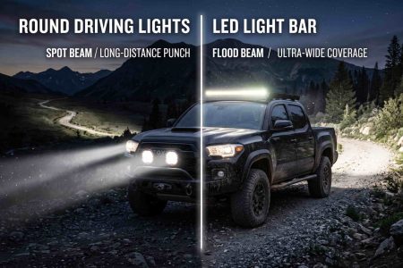
The distinction is especially important when comparing photographs. A flood beam can fill a large area with visible light and look impressive in a wide camera frame. A concentrated beam can create a smaller visible patch while illuminating a distant target more effectively. Neither image alone tells you whether the beam fits your task. The camera exposure and the target distances must be controlled before the comparison starts to mean anything.
For background on complete-lamp output and component totals, read Raw Lumens vs Effective Lumens. Treat a quoted lumen number as an invitation to ask how it was measured. Was it obtained from the complete lamp or calculated from component datasheets? At what voltage and temperature? After how much operating time? Comparing consistent answers to those questions is more useful than inferring performance from a second horizontal row.
Beam distribution is a separate decision
Choose the optical version before deciding whether a row configuration meets the need. Spot, flood, driving, combo and scene are commercial descriptions whose actual distributions vary between product families. A name can help you find the intended version, but a name alone does not define a precise beam shape. Look for an intensity plot, an illuminance map or a clear statement of the measurement geometry for the exact part number you are considering.
Manufacturer examples show why packaging and beam selection must be separated. RIGID’s E-Series PRO page identifies a double-row product family and offers several optical choices. That is evidence about that family, not a rule that every double-row bar has a particular distribution. The historical Baja Designs S8 datasheet likewise lists multiple optical versions within the same size category. Its older figures should not replace current part-specific information.
In a beam map, examine more than the brightest central value. Find the region where illumination remains useful for the job, the transition from center to shoulder and any gaps between optical regions. A pronounced hot spot can be desirable for distance but distracting during close work. A broad beam can be desirable for maneuvering but inadequate for a distant target. The appropriate balance depends on the viewing distance and the operator’s task.
If you combine two lamps, consider how their distributions overlap. Two broad beams can create a very bright central overlap without improving the outer work area proportionately. Two narrow beams aimed apart can leave a gap directly ahead. A well-planned combination uses each lamp for a defined area. It does not assume that doubling the lamp count or adding another row automatically produces an even, continuous field.
The same reasoning applies to selecting a light bar alongside the vehicle’s existing lighting. Identify the actual deficiency first: an unlit shoulder, an inaccessible work area, a poorly illuminated maneuvering zone or insufficient distance under permitted conditions. Then choose optics that address that deficiency. Purchasing a second row because the existing system feels inadequate skips the diagnostic step and can leave the original problem unresolved.
Reading lumens, candela and lux together
Lumens describe luminous flux, candela describes luminous intensity in a direction and lux describes illuminance falling on a surface. These measures answer different questions. A buying comparison becomes more meaningful when you know which one supports the manufacturer’s claim. Total flux is relevant to overall output, directional intensity is relevant to concentration and illuminance maps are relevant to the distribution at a specified distance. No single number describes the entire experience of seeing with a lamp.
For an idealized point-like source in the far field, illuminance on a surface normal to the beam can be estimated as intensity divided by distance squared. If the intensity is 40,000 candela, the simplified calculation gives 4 lux at 100 meters. At 200 meters it gives 1 lux. This hypothetical arithmetic illustrates the distance relationship. It does not account for atmospheric loss, target reflectance, mounting geometry or the many conditions that affect practical recognition.
That square relationship explains why doubling intensity does not double a quoted distance to the same illuminance threshold. Under the simplified model, twice the intensity increases the distance by the square root of two, about 1.41. Four times the intensity would be needed for twice the distance to the same threshold. Row count cannot be inserted into that calculation unless it is supported by measured intensity for the exact lamps.
A distance-to-one-lux claim also needs context. One lux at a particular point is a photometric threshold, not a guarantee that a driver can recognize every obstacle at that distance. Dark clothing, low-reflectance surfaces, weather and glare can change what is visible. A well-marked reflective sign may be recognized much farther away than a low-contrast object. Do not translate an advertised reach into a safe speed or a universal recognition distance.
Ask for the beam map associated with the claimed distance. A very narrow beam can achieve a long central threshold distance while leaving surrounding areas comparatively dark. A broader distribution may have a shorter central threshold but provide more usable context. When the task requires both distance and width, compare both regions instead of selecting the longest single number. The best evidence states the test setup and allows the reader to understand what the number includes.
Measure the entire installed envelope
Before choosing a bar, measure the usable opening in three dimensions. Record width, height and depth, then identify nearby components that can move, become hot or require service. Include the path that the lamp must follow during installation. A body that fits after assembly may still be impossible to insert without removing other parts. An accurate check considers access and assembly order as well as the final parked position.
Use the manufacturer’s complete dimension drawing and the bracket drawing together. A nominal twenty-inch product name may identify a product class rather than the exact distance between mounting points. End caps, side brackets and fastener heads can extend beyond the illuminated portion. The connector may need additional clearance for the plug and a reasonable cable bend. Record those features individually rather than assuming the advertised length covers the whole assembly.
Height deserves the same treatment. A single-row bar can have lower brackets that increase its installed height beyond the face height. A double-row bar can sometimes mount with a different interface that reduces the extra space needed around it. Evaluate the actual combination, including the angle adjustment range. If aiming requires rotating the housing, check the envelope at the intended aim position rather than only with the body lying flat.
Create a cardboard template when the opening is difficult to visualize. The template should reproduce the body outline and the important protrusions, not only the illuminated face. It can reveal an interference point before purchase, but it cannot prove structural strength, cooling performance or sensor compatibility. Treat it as an inexpensive geometric check. Final fitment still depends on accurate dimensions and approved installation instructions for the vehicle and bracket system.
Leave access for future inspection. A tightly packed lamp that can only be reached after dismantling a bumper can make routine checks expensive. Consider whether you can see the connector seal, inspect the cable where it leaves the housing and retighten fasteners as the manufacturer permits. A little additional clearance may be worth more than the visual neatness of a flush fit if the installation will face vibration, mud or frequent servicing.

Grille openings and partial beam obstruction
A grille-mounted bar needs a clear optical path. The grille may appear open from directly in front while blocking parts of the beam at other angles. Horizontal slats can mask one portion of a taller optical face. A slim bar may sit between the slats more easily, but that possibility must be checked against the actual pattern and position. A photograph of a neatly installed housing does not demonstrate an unobstructed beam.
Check the path from each optical region to the intended target area. A slat close to the lamp can intercept different rays as the lamp is aimed up or down. The result may be a changed distribution, irregular shadows or unwanted reflections from surrounding surfaces. Moving the housing forward can sometimes reduce masking, but it may introduce exposure, structural or clearance problems. Evaluate the whole installation rather than improving one variable in isolation.
Avoid estimating loss from the percentage of open grille area alone. Light is not necessarily distributed evenly across the optical face or through every direction. A grille that blocks a small part of the face may intercept an important beam region. Another may block a visually large part of the face but affect a less critical direction. A useful assessment compares the installed beam with an unobstructed reference under controlled conditions.
The vehicle’s cooling and sensing functions also matter. Do not assume that space in front of a radiator, camera or radar unit is spare capacity for an accessory. A bar and its brackets can occupy airflow paths or interfere with a sensor’s field. Compatibility must be established from the vehicle and accessory documentation. Row count does not answer these questions, and a smaller housing does not automatically remove every interference risk.
When you cannot obtain reliable compatibility information, choose an alternative location or consult the appropriate installer. The cost of relocating a light after purchase can exceed the difference between two candidate bars. A mounting solution that preserves the vehicle’s functions and provides a clear beam is usually a better starting point than forcing a preferred light into an attractive but unverified opening.
Brackets, vibration and mechanical load
The mechanical comparison should include mass, lever arm and mounting interfaces. A heavier lamp places a different demand on the support than a lighter one, but row count alone does not establish weight. The distance from the support to the lamp’s center of mass also affects loading. A modest increase in overhang can matter when a vehicle encounters repeated bumps. Compare the complete assembly and the approved bracket system, not just the housing description.
A bracket that holds a lamp securely while the vehicle is parked may still flex during operation. Flexing can make the beam move relative to the ground, reduce visual consistency and load fasteners repeatedly. Adding a second row does not inherently create this problem, but a taller or heavier assembly may expose weaknesses in a mount designed for a different load. Match the bracket’s stated application and installation method to the exact lamp.
Use the specified fasteners, tightening procedure and support points. Do not invent a universal torque value or replace the manufacturer’s hardware merely because another bolt looks similar. Material, thread engagement, coatings and locking methods can affect the connection. If the instruction set does not cover your mounting arrangement, obtain clarification before drilling or modifying a structural part. A useful buying decision includes the information needed to install the product correctly.
Inspect adjustment access as well as strength. Some side brackets require room for a tool on both sides of the lamp. A hidden installation may make aiming difficult once the bodywork is reassembled. Check whether the lamp can be positioned, tightened and rechecked without bending the bracket or leaving a fastener partially engaged. Ease of adjustment is a practical feature, especially when the vehicle’s load or the intended work area changes.
After installation, follow the manufacturer’s inspection intervals and watch for movement, rubbing or damaged finishes around the attachment. Document the initial position so that later changes are recognizable. If a lamp repeatedly loses aim, find the mechanical cause rather than continually retightening it beyond the specified limits. The solution may involve the support or bracket arrangement rather than choosing a different number of rows.
Input current and harness suitability
Electrical demand must come from the exact product specification. A single-row lamp can draw more current than a smaller double-row lamp, and two similarly sized lamps can operate at different power levels. Compare the stated input current, operating-voltage range and any startup or control requirements. The electrical system sees the complete load, including optional functions, rather than the number of visible optical cells.
For a simple illustration, a load that actually consumes 120 watts at 12 volts draws about 10 amperes because current equals power divided by voltage. At 24 volts, the same input power corresponds to about 5 amperes. A real LED driver’s behavior across voltage can differ from that simplified example, so use the manufacturer’s current data when available. Do not assume the lamp’s nominal wattage remains exactly constant under every operating condition.
The harness needs to support the lamp, its route and the installation environment. Relevant details include conductor size and material, total circuit length, temperature exposure, connectors, fuse protection and switching hardware. A harness included with one product is not automatically suitable for a different lamp, even if both use a similar connector. Check the ratings and the manufacturer’s instructions before transferring a harness from a previous installation.
Fuse selection also requires care. A fuse protects the circuit within the design limits of the wiring and associated components; it is not simply a way to stop nuisance interruptions by choosing a larger number. If the specified fuse repeatedly opens, diagnose the cause. Do not increase its rating beyond the documented design. For installations involving vehicle control modules, battery-monitoring systems or unfamiliar wiring, obtain the required vehicle-specific guidance.
Include every simultaneous load in your planning. A main light bar, work lamps, a refrigerator and other accessories can create a different demand from the light bar alone. A vehicle’s electrical capability also varies with operating conditions. The existence of a high-output alternator does not by itself prove that the installation has spare capacity for an additional accessory. Review the vehicle and accessory requirements together, then confirm the installed system operates within their limits.
Voltage drop can erase an apparent advantage
A light comparison made with different supply circuits can confuse lamp performance with wiring performance. Resistance in cables, terminals or connections causes a voltage drop when current flows. A lamp receiving less voltage than intended may operate differently, depending on its driver and protection behavior. Testing the circuit under load is therefore more informative than checking only for voltage at an unplugged connector. Fluke’s automotive guidance explains the value of loaded voltage-drop testing.
Consider a hypothetical circuit with 0.10 ohm of combined unintended resistance. At 10 amperes, the voltage drop is 1 volt and the power dissipated in that resistance is 10 watts. At 20 amperes, the drop is 2 volts and the dissipated power is 40 watts. These numbers illustrate the relationships V = I × R and P = I² × R. They are not suggested limits for any particular harness or lamp.
This example shows why a higher-current candidate may require more attention to the supply circuit. A small resistance that appears tolerable with one load can become more consequential with another. The appropriate correction is to identify and repair the circuit issue using the approved design, not to blame the double-row layout. Conversely, a lower-current bar should not be used to conceal a damaged or poorly designed connection that needs correction.
For safe measurements, follow the meter instructions and the vehicle’s procedures. Keep leads clear of moving parts and hot surfaces, and do not place a meter set for current measurement directly across a power source. Voltage-drop testing generally measures the voltage difference across a selected part of the loaded path. If you cannot identify the circuit safely or do not understand the instrument settings, stop and ask a qualified automotive electrician to perform the check.
Record the supply voltage at the lamp during a controlled comparison. That record helps explain a result that changes after a harness repair or a different operating condition. It also prevents an unfair comparison in which one lamp is tested on a short, well-supported circuit and another on a long, resistive route. A buying decision should distinguish the lamp’s characteristics from the quality of the installation supplying it.
Cooling and sustained output
LED lamps convert electrical input into light and heat. Their thermal design includes the path from the LED through the board and housing to the surrounding environment. A larger body may offer more cooling area, but housing size alone does not prove better thermal performance. Material, interfaces, driver settings, fin geometry and installation conditions all affect the result. Compare documented sustained output rather than assuming that either a slim or a tall housing handles heat better.
Output measured immediately after startup can differ from output after the lamp reaches a steadier thermal condition. Some lamps reduce drive current as temperature rises; others maintain output within their specified operating conditions. A useful comparison states the warm-up period, ambient temperature, supply voltage and whether air moved around the housing. Without those details, a short demonstration may show an initial condition that is not representative of a longer work session.
The mounting location changes cooling conditions. A recessed installation can limit airflow or place the lamp near a hot component. Mud can cover surfaces intended to release heat. A bar positioned in open air may experience a different environment from the same bar behind a restrictive panel. Neither row configuration is exempt from these influences. The most relevant test resembles the installed environment while staying within the manufacturer’s stated operating limits.
Do not interpret a housing that feels hot as a complete diagnosis. A warm housing can indicate that heat is reaching the external structure, while a cooler surface does not prove that the LED junction is cool. Surface temperature, internal component temperature and ambient temperature are different quantities. Avoid touching a lamp to estimate safety or performance; use the prescribed inspection methods and allow the assembly to cool before handling it.
A buyer can ask a straightforward question: what performance is reported after stabilization, and under what conditions? If only a peak lumen value is available, note that limitation in the comparison. You may still choose the product for a documented application, but you should not turn the initial figure into a promise of constant output throughout a long stationary operating period.
Color, lens choice and visual comfort
Row count does not determine color temperature. A single-row or double-row product can use different LED spectral characteristics, clear lenses or colored filters. Evaluate the exact optical and color version. A buyer who compares a cool-white narrow beam with an amber broad beam is changing more than one variable, making it difficult to attribute the perceived difference to the number of rows.
Color temperature describes chromaticity in a particular way; it is not a complete description of the spectrum or the visual experience. A lower stated kelvin value does not automatically guarantee improved visibility in every environment. Likewise, a higher value does not automatically mean greater usable brightness. Target color, background, reflections and the observer’s adaptation all matter. Treat simple statements that one color always sees farther as claims requiring relevant evidence.
Visual comfort also depends on where the light falls. Bright illumination close to the vehicle can dominate the driver’s view while the distant area remains relatively dark. A lamp can increase visible foreground brightness without improving recognition where the vehicle is headed. Reflections from a hood, windshield, tools or wet surfaces can further affect the experience. The appropriate solution may be a different beam distribution or position rather than another row.
If a candidate uses separate backlighting, determine its purpose and wiring requirements. Decorative or position functions should not be included in the main beam’s performance comparison unless the manufacturer explicitly defines them that way. Additional wires may require separate control and protection. The visual appearance of a glowing housing while parked is different from the main lighting function that illuminates the task area.
Evaluate comfort during a controlled stationary test before relying on the installation. Use representative targets and check from the actual operating viewpoint. A camera cannot reproduce every aspect of human adaptation or glare, so combine photographs with direct observation and relevant measured data. Record the conditions, and avoid turning one subjective impression into a universal statement about all single-row or all double-row products.
Environmental protection and service life
The number of rows says nothing reliable about sealing quality. Environmental durability depends on the enclosure, seals, cable entries, connectors, materials and the applicable test conditions. A protection rating describes specified tests, not unlimited resistance to every combination of pressure, heat, chemicals and aging. Request the exact rating and its basis for the lamp and connector assembly rather than treating the visible shape as evidence of waterproof construction.
Check whether a rating applies with the supplied connector fully mated and correctly installed. A sealed housing can still be part of an installation with an exposed splice or damaged plug. The cable route and strain relief deserve as much attention as the lens seal. If the product includes an unusual connector, determine whether compatible replacement parts and approved repair procedures are available before purchase.
Life-expectancy language also needs context. A quoted LED component lifetime is not necessarily the expected service life of the complete lamp. Drivers, seals, connectors and mounting parts can fail through different mechanisms. Temperature and operating conditions affect the assembly. Ask whether the figure concerns a component, a complete-lamp test or a warranty provision. These are different forms of evidence and should not be substituted for one another.
Routine cleaning should follow the manufacturer’s instructions. Do not assume a product’s high-pressure test designation permits any cleaning nozzle at any distance with any chemical. Surface damage or seal deterioration can occur outside the specified conditions. Protect cooling surfaces from persistent buildup and inspect the lens for damage that changes the beam. A clear maintenance procedure is more useful than a vague description of the housing as rugged.
Serviceability can influence the long-term buying decision. Some products have replaceable lenses or parts; others are sealed assemblies intended for replacement. Neither approach is automatically superior for every buyer. Compare the supported service process, the availability of parts and the practical cost of removal. A lamp that fits your task and can be maintained within its approved process may be a better value than a more powerful candidate with uncertain support.
Road use and approval are independent of row count
An accessory’s row configuration does not establish permission to use it on public roads. The relevant questions concern the lamp’s function, applicable approval or certification, installation requirements and local operating rules. A commercial name such as driving beam can describe a product’s intended pattern without proving legal road use. Check the documentation for the exact part number and your jurisdiction before planning a road-use installation.
Different approvals address different subjects. A claim about electromagnetic compatibility does not by itself establish compliant light distribution or permitted installation. A protection rating does not establish road approval either. Ask the seller to identify the actual regulation or standard, the approval scope and the applicable product version. If a label is unclear, do not infer its meaning from another product in the same family.
Vehicle requirements also matter. Adding a lamp can affect existing lighting, sensors or mounting arrangements. The rules governing an installed vehicle can differ from the rules governing the sale of a component. A product approved for a particular function still needs an installation that meets the relevant conditions. Because these requirements vary, this buying guide does not offer a universal legal conclusion for every auxiliary light bar.
For a comparison of lamp types and intended uses, see LED Light Bars vs Driving Lights. Use that distinction to organize your questions, then verify the current local requirements through the appropriate authority and the exact manufacturer documentation. If your planned use is exclusively on private land or at a worksite, other operating and safety requirements may still apply; permission to access the land does not resolve every equipment question.
Make the permitted operating mode part of the buying specification. A lamp that must remain off during most of your intended journeys may provide less value than a different documented solution. The switch arrangement should support safe operation and avoid confusing the driver. Resolve those requirements before purchasing, because changing the light after discovering a use restriction can also require changing brackets, wiring and controls.
Match the light to the actual task
When comparing single row vs double row LED light bars, start by describing the task in plain language. An operator reversing a trailer into a dark yard needs a different view from someone inspecting equipment beside a parked vehicle. A trail user seeking distant context under permitted conditions has another requirement. These descriptions lead to target areas, viewing positions and operating durations. They are more useful than beginning with a preference for a taller or thinner housing.
For stationary work, identify the working surface and the people who may enter the lit area. A broad distribution may be appropriate when tools, couplings or inspection points are spread across a space. A highly concentrated beam can create a bright patch and deep contrast around it. Mounting position should let the operator see the relevant surfaces without repeatedly facing the lamp. Row count is secondary to those requirements.
For slow maneuvering, evaluate near and peripheral areas from the driving position. A forward-facing bar may not illuminate a hitch, a rear corner or a side obstacle. Buying a larger forward bar will not necessarily solve a coverage problem behind the vehicle. A dedicated lamp with the correct orientation can be more appropriate. Identify the missing view rather than increasing the output of a lamp facing the wrong direction.
For trail use, assess the beam under the actual permitted operating conditions and keep speed appropriate to verified visibility and terrain. No accessory’s advertised range establishes a safe speed. A narrow central beam may reveal one distant feature while leaving nearby hazards outside the illuminated region. A broader beam may improve context but create reflections from close vegetation. Consider how the entire lighting system works together from the driver’s viewpoint.
SAEC’s LED Light Bars and LED Work Lights provide starting points for different lighting tasks. Compare the exact product specifications and request relevant test information before selecting a model. These category links do not establish fitment, measured superiority or road-use permission for any particular vehicle or installation.
A fair stationary comparison method
A controlled comparison should change one important variable at a time. Use the same mounting height, target layout, aim reference and observation position when those conditions can be matched safely. Record the exact lamp versions and supply conditions. If the products require different installation arrangements, state that difference openly. A comparison with clear limitations is more useful than a dramatic demonstration that hides the conditions responsible for the result.
Choose a private, permitted test area with no traffic or people exposed to the beams. Position representative targets before energizing the lamps, and keep the vehicle stationary. Targets can include surfaces with different reflectance and objects at different positions across the intended work area. The purpose is to understand coverage and recognition under controlled conditions, not to encourage driving beyond the visible area or looking directly into intense light.
Allow each lamp to operate according to the agreed test procedure and manufacturer’s limits. Record the elapsed time so that an immediate startup image is not compared with a warmed lamp. Measure or record supply voltage at the lamp where safe and appropriate. Note ambient conditions, surface moisture and any obstructions. These details help separate a difference in product behavior from a difference in test conditions.
If you use a lux meter, follow its instructions and keep measurement geometry consistent. The sensor’s position and orientation affect readings. A grid of points can describe distribution better than one reading at the brightest point. Do not assume a low-cost meter provides a laboratory-quality result or use it to certify compliance. Treat field measurements as comparative observations within their stated limitations and retain the procedure with the results.
Photographs should use fixed exposure, white balance, focal length and viewpoint for a meaningful comparison. Automatic camera settings can make two different outputs look similar or exaggerate their difference. Keep original images and the settings record. Avoid presenting a composite image without explaining the method. Direct observation and measured data can complement photographs, but neither should be converted into a broader claim than the test supports.
Eight checks before placing an order
The first check is the exact part number. Product families often include different lengths, optics, colors and control options. A review of one version may not describe the version in your cart. Save the relevant product page and installation document with the quotation. If the seller’s image, title and specification conflict, ask for clarification before using any of those details to make a fitment decision.
The second check is the beam evidence. Request the selected optical version’s distribution and the conditions behind its advertised range or flux. The third is the complete installed envelope, including brackets and connector clearance. These two checks establish whether the light can occupy the available space and perform the intended task. A candidate that fails either one should be reconsidered before accessory costs are added.
The fourth check is the electrical requirement. Match the lamp to a documented supply, harness, fuse and control arrangement. The fifth is the thermal condition: determine whether the reported performance is initial or stabilized, and whether the planned location respects the operating limits. These checks are connected, because electrical input and the installed environment can influence the lamp’s sustained behavior during actual use.
The sixth check is environmental and mechanical support. Confirm the applicable sealing information, the approved mounting system and the service process. The seventh is permitted use for the intended location and operating mode. The eighth is total ownership cost, including installation, any required supporting parts and realistic maintenance. A cheaper lamp can become more expensive when these items are discovered after purchase.
Write the answers in a small comparison sheet and identify any unanswered question. You do not need to assign an artificial numeric score to every item. Some requirements are pass-or-fail constraints; others are preferences. A lamp with a higher score in brightness should not compensate for a failed clearance or compatibility requirement. Select from the candidates that satisfy the fixed requirements, then compare the advantages that remain relevant to your task.
Worked examples of three buying decisions
Consider a hypothetical vehicle with a shallow vertical opening and adequate space across its width. The buyer wants a forward auxiliary beam for permitted private-land use. Candidate A is a slim bar with a documented bracket drawing; Candidate B is a taller bar with higher stated flux. If Candidate B’s body masks part of the opening or prevents the required adjustment, the higher number does not solve the installation problem. Candidate A remains worth evaluating if its beam covers the required area.
Now consider a stationary equipment application with a broad work area and a strong, documented mounting point. Here, height may be less restrictive than distribution and sustained operation. A double-row candidate might offer useful additional flux, but the buyer should compare the illuminance map over the actual work area and check the electrical load. A narrow double-row beam that concentrates light beyond the working surface can be less suitable than a lower-output broad lamp.
In a third example, an owner already has a functioning bar but feels that the scene is uneven. The problem could be a grille obstruction, inappropriate aim, a missing side-lighting zone or an electrical supply issue. Replacing the existing bar with a second row without checking these possibilities can reproduce the same uneven scene. The economical first step is to document where visibility is lacking and inspect the existing installation under controlled conditions.
These examples do not nominate a winner by housing category. They illustrate a decision sequence: define the task, eliminate candidates that fail fixed constraints, compare evidence for the remaining candidates and confirm the installed result. A buyer can legitimately choose a single-row lamp in one case and a double-row lamp in another without contradicting the method. The conditions, rather than a universal preference, determine the choice.
If an installer proposes a particular product, ask how it addresses the specific constraint you identified. A useful answer explains the clearance, optical choice, harness and support arrangement. An answer based only on how impressive the light looks or how many LEDs it contains leaves the important questions open. Keep the proposal specific enough that the completed installation can be checked against the original requirement.
Common specification traps
One common trap is comparing calculated component lumens with complete-lamp measured lumens. The figures may use the same unit while describing different parts of the system. Another is comparing different optical versions under one family name. A third is treating a nominal length as the distance between brackets. These mistakes can make a double-row candidate seem automatically superior or make a single-row candidate seem easier to fit than it actually is.
Watch for mixed measurement conditions. A specification at one supply voltage may not be directly comparable with another at a different voltage. Initial output may not match stabilized output. A distance figure may use a different illuminance threshold or measurement convention. When conditions are not stated, label the comparison as incomplete rather than calculating precise ratios from numbers that may not share a common basis.
Avoid using marketing photographs as dimension drawings. A bar shown on one vehicle does not prove it fits another year, trim, bumper or accessory arrangement. Vehicle modifications can change the available space and the compatibility of brackets. If fitment is claimed, look for the exact application and the installation instructions. A generic universal description usually means additional verification is needed, not that every installation is straightforward.
Warranty language can also be misunderstood. A long warranty does not automatically cover every installation method, environmental exposure or service action. Read the relevant terms and ask about parts support and the claims process. Distinguish a product’s advertised durability from the procedures needed to maintain warranty coverage. These practical details may be more important to a frequent operator than a small difference in an initial output claim.
Finally, do not confuse confidence with certainty. A clear product page and a careful installation check reduce uncertainty but do not eliminate every real-world variable. Keep the conditions attached to your conclusion: the selected optical version, the installed location, the measured supply and the intended task. That approach gives you a decision that can be reviewed later if the vehicle, accessories or operating needs change.

Questions buyers often ask
Is a double-row light bar always brighter?
A double-row layout does not guarantee greater measured output than every single-row product. Compare the complete lamps using the same measurement basis and conditions. LED type, drive level, optics and thermal behavior can differ between designs. Even when one bar produces more total lumens, it may not provide more illumination in the specific area you need. Ask for the selected optical version’s beam data rather than relying on the visible row count.
Does a single-row bar always fit behind a grille?
No. A slim face can help with one clearance dimension, but the body depth, brackets, connector and adjustment envelope still need checking. Grille slats can obstruct the beam, and nearby vehicle components can create compatibility constraints. Use a complete drawing and the relevant vehicle-specific installation information. If the necessary measurements or sensor requirements are unknown, treat fitment as unconfirmed instead of turning the word slim into a guarantee.
Can I reuse my existing harness when changing bars?
Only if the exact harness and its installation are documented as suitable for the replacement lamp. Check current demand, operating voltage, connectors, fuse protection, switching and the full circuit route. A similar plug does not establish equal electrical ratings or control behavior. If the new load is greater or its functions differ, the existing installation may need changes. Obtain the manufacturer’s guidance or a qualified installer’s assessment rather than assuming compatibility from appearance.
Should I buy the longest bar that fits?
Length is one packaging variable, not the final goal. A longer bar can add optical positions, mass, electrical demand and mounting complexity without necessarily improving the required view. Choose the beam and output needed for the task, then select a size that fits the approved mounting arrangement. Leave clearance for adjustment and service. If several lamps satisfy the task, compare their total installation and ownership requirements before choosing the largest.
Does a combo beam remove the need to compare optics?
No. Combo describes a combination chosen by the manufacturer, but its balance and distribution vary. One product may devote a different portion of its optics to distance or width than another. Review the actual map, the target area and the installed position. A combo beam can be useful, but the name does not prove that it supplies the right amount of light in every area important to your particular application.
What should I request if a seller supplies only watts and lumens?
Ask for the exact part number, complete dimensions, input current over the operating range and a beam plot or relevant illuminance data. Also request the measurement basis for lumens, the conditions for sustained output, installation instructions and approval information for the intended use. A seller may need to obtain some information from the manufacturer. Until the relevant gaps are resolved, your comparison remains partly uncertain, even if the headline figures look precise.
How should I compare single row vs double row LED light bars for a worksite?
Define the work area, viewing positions and operating duration first. Compare distribution over that area, sustained performance, electrical demand and the suitability of the complete installation. Consider glare toward workers and reflections from equipment. A broad, appropriately placed lamp may serve the task better than a more intense forward beam. Row count can help describe the available products, but it should not substitute for evidence about the working surface and the operator’s actual view.
Can a field test prove road legality?
No. A field test can help you understand coverage and installation behavior within its limitations, but it does not replace the applicable certification, approval or legal requirements. An attractive beam pattern or a satisfactory lux reading does not establish compliance. Verify the exact lamp function and documentation with the relevant current rules. Where requirements are unclear, ask the appropriate authority or a qualified specialist before using the accessory on public roads.
Build a purchase specification you can verify
A useful purchase specification states the task, location, fixed clearance, required optical version and relevant operating conditions. Include the supported mounting system and electrical arrangement. This document does not need to be long, but it should be specific enough that a seller or installer can confirm what is being supplied. A requirement such as maximum brightness is difficult to verify; a requirement linked to a defined target area and documented beam information is more practical.
Keep evidence with the specification. Save the dimension drawing, installation instructions, applicable product data and correspondence resolving any conflicts. Record the date because product families and listings can change. If you later need replacement parts or a warranty assessment, this record helps identify the exact version and installation basis. It also reduces the chance that a review of a different optical option becomes part of your decision by accident.
After installation, verify the items that can be checked safely: the specified position, clearances, cable support, connector condition, controls and stationary lighting result. Refer unfamiliar electrical or structural checks to the appropriate professional. The installation should match the documented plan, and any necessary change should be evaluated on its own merits. Do not allow a last-minute bracket adjustment to introduce an unreviewed interference or a strained cable route.
If the result falls short, describe the shortfall precisely. Is a target area too dark, is a reflection distracting, does the beam move, or does performance change with operating time? Each observation leads to a different investigation. Increasing row count is only one possible equipment change and may not address the cause. A precise description makes follow-up with the seller or installer more efficient and avoids purchasing another lamp without learning from the first installation.
The practical decision in single row vs double row LED light bars is therefore conditional: select the complete product whose documented beam and installed requirements fit your task. Use row count to describe the housing, measured evidence to compare performance and a verified installation to deliver the result. Keep the product-specific limits attached to the conclusion so that a change in vehicle, location or operating need triggers a fresh check.
Updated October 13, 2026.
Sources
- RIGID Industries: E-Series PRO 40 Inch, accessed October 13, 2026. Product-family layout and optical choices only; inconsistent dimension fields were not used.
- Baja Designs: S8 historical datasheet, accessed October 13, 2026. Used to illustrate that a size category can offer multiple optical versions; older figures are not treated as current specifications.
- Fluke: Electrical automotive troubleshooting and voltage drop, accessed October 13, 2026. Supports loaded-circuit measurement principles; worked values in this guide are hypothetical calculations.
 by


