


On this page
Quick answer
The best mounting point is the one that puts the tested beam on the area you need to see while the lamp remains secure, serviceable, correctly aimed, and compatible with the vehicle. Your LED light bar mounting position should emerge from that task and vehicle fit check. A roof mount can give a long sight line and clear some front-end obstructions, but height alone does not make a light bar brighter or guarantee more useful distance. A bumper or grille mount can keep the source lower and closer to the vehicle’s forward structure, but it may leave a nearby ground shadow, restrict airflow, or make the lamp vulnerable to mud, stones, and impacts. The product’s optics, mounting geometry, aiming range, vehicle load, wiring, and operating conditions all matter.
Before you buy, answer five questions: What region must be illuminated? What is the actual usable space between mounting points? What parts could block the beam or its cooling path? Can the brackets carry vibration and impact loads? And do vehicle instructions and local rules allow the intended installation and use? These questions are more useful than assuming that the highest or largest position is always best. This guide compares common roof, grille, and bumper arrangements and explains how to check a real vehicle without treating a universal chart as proof of fitment.

Start with the job, not the mount
Mounting discussions often begin with a photo of a completed truck. That is understandable: a roof bar, grille bar, and bumper bar look different, and the position changes the vehicle’s appearance. But a photograph does not tell you how the beam performs on an unfamiliar trail, how it behaves when the vehicle is loaded, whether a rack blocks part of it, or whether a bracket is made for your model year. Start by describing the work the lamp must do.
For a low-speed trail, a driver may need to see a broad area near the front tires, the edges of a narrow track, and small obstacles on the ground. A roof-mounted narrow beam can project far ahead while leaving the close foreground less illuminated than expected. A low bumper lamp can put light close to the vehicle but can be hidden by a winch, bull bar, license plate, recovery gear, or a steep approach angle. Neither description is universal: lamps differ in optical distribution, and their installed angle changes where the light lands. Define a zone, such as “road ahead beyond the headlamps,” “ground immediately in front of the bumper,” “work area behind the truck,” or “side of vehicle during a turn,” before selecting hardware.
Next, define the conditions. Consider vehicle speed, terrain, weather, passenger or cargo load, whether the lamp will be used only off-road, and how often it must be removed or serviced. A vehicle that sees highway use, garages, low branches, wash racks, and tight parking structures has different constraints from a dedicated trail rig. A delivery van used in a yard may value a low, protected installation that lights work near the bumper. A roof rack used for cargo may leave no clear crossbar or may be loaded above the lamp. A position that works on an unloaded display vehicle can fail on the same vehicle with a rooftop tent or an open hood.
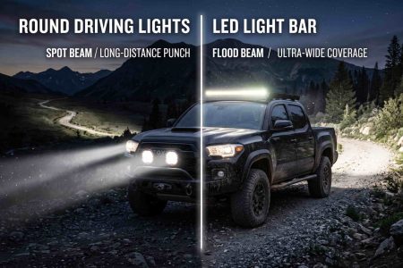
Write the problem in one sentence before shopping. For example: “I need a wide, controlled beam to see trail edges at walking speed, without lighting my hood or blocking the grille.” That statement does not select a product, but it creates a basis for comparing pattern, height, brackets, size, and switches. It also exposes the details that need verification. If the desired beam must cover both far distance and close ground, one bar may not be the best answer; separate lamps with different optical patterns may be easier to aim and control. For a pattern explanation, see SAEC’s spot versus flood LED work-light guide.
Understand height, aim, and beam shape
Moving a lamp higher changes the geometry between the source and the illuminated surface. It does not change the lamp’s rated luminous flux, the beam’s peak intensity, or the quality of its optics. Height can affect how far a direct line of sight extends over some terrain, but it can also increase the chance that the light strikes a nearby surface at a shallow angle, catches airborne particles, reflects from a hood or roof, or shines toward another person’s eyes. A high mount can improve access around certain obstacles while making glare management more important. The actual outcome depends on where the light is pointed and what lies in front of it.

Beam pattern is a separate choice from mounting location. A narrow spot distribution, a broad flood distribution, a driving pattern, or a combination optic sends light into different angular zones. Two lamps at the same height can produce very different useful coverage. Two identical lamps in different positions can also illuminate different parts of the scene. A product page that shows lumens alone cannot tell you whether the light will reach a desired point or spread across a useful width. Look for complete-lamp photometry or a clearly identified beam diagram, and check whether the chart is for the same model, optic, and operating mode you plan to buy.
The vehicle can interfere with that beam. A bar mounted close to a roof edge might have a blocked upper or side angle. A wide flood optic behind a grille may send part of its output into grille bars. A low lamp can be shadowed by the bumper or by a winch fairlead. A roof lamp may reflect from the hood, windshield, or a light-colored roof rack. A mounting position should therefore be evaluated from the driver’s intended viewing direction and from the lamp’s optical axis, not only from a side-view photograph.
Avoid a simple claim such as “roof lights throw farther” unless it is tied to a specified lamp, aim, test surface, and measurement. A more careful statement is that a higher source can have a longer unobstructed line of sight over some near-field obstacles, while useful illumination still depends on intensity distribution, aim, vehicle pitch, and atmospheric conditions. The buyer’s task is to match an actual beam to the desired scene and confirm that the brackets let the lamp point there. If the available adjustment range cannot put the beam where required without illuminating the hood or roof, the mount is not suitable even if its location looks attractive.
Roof mounting
A roof or roof-rack mount is common because it raises a bar above some front-end obstructions and can provide a broad forward view from the vehicle’s highest practical structure. It may be useful when the light must clear a front bumper assembly, when the vehicle already has a load-rated rack with approved accessory points, or when the owner wants long-range illumination ahead on private land. Some manufacturers offer roof-specific brackets, fairings, and bar lengths. Those kits are model- and rack-dependent; the word “universal” should not replace a fit check.
Roof mounting adds height, and height brings practical costs. Measure the finished vehicle, including the lamp, brackets, rack, rooftop cargo, antennas, and any flexible wiring. Recheck garage doors, parking structures, ferry decks, tree branches, trail obstacles, and vehicle transport limits. A bar can become the highest and most exposed item on the truck. If the rack flexes or the brackets loosen, vibration loads can be transmitted repeatedly into the lamp and body. Fastener choice and torque should follow the rack and lamp instructions; do not assume a bolt that physically fits is approved for the load or material.
Air movement and noise deserve a specific check. A bar, bracket, cable, and fairing alter airflow around the roof. Some installations create wind noise, whistle, or turbulence. A fairing may reduce noise for one rack and one product geometry, but it is not proof that every combination will be quiet. Roof position can also influence drag and fuel or energy use, although the effect depends on the vehicle, speed, rack, and total shape. Avoid quoting a universal consumption penalty without a test for the actual setup.
The lamp’s light may reflect off the hood, windshield, roof rack, or cargo. A shiny light bar housing, painted hood, or dusty windshield can make forward visibility worse when the lamp is switched on. The driver’s eyes adapt to the lit nearby surfaces, making the distant scene seem darker. Before final tightening, test for glare in a safe, dark area with the vehicle stationary and the beam directed at a non-public target. Adjust the lamp only within its intended range and confirm that it stays put after a drive over representative terrain. If the vehicle has a sunroof, roof-mounted sensors, a roof antenna, or side-curtain airbags near a proposed cable route, follow the vehicle maker’s instructions or use a qualified installer.
Roof installation is a poor choice when the vehicle regularly enters spaces with limited overhead clearance, when cargo blocks the bar, when the rack lacks an approved mount, or when the driver cannot manage hood and windshield reflections. It may also be inconvenient if the bar must be removed often, because safe access can require a ladder and two-person handling. The roof is a location to evaluate, not an automatic upgrade.
Grille mounting
A grille or front fascia location can create a compact, integrated appearance and can place the lamp near the vehicle’s original forward lighting. A smaller bar may fit between grille features or into a model-specific opening. This can reduce how far the lamp projects from the front end and may keep it below some overhead obstacles. An application-specific bracket can sometimes use existing mounting points and avoid drilling, though the product documentation must confirm that for the exact vehicle year and trim.
Grille openings are not empty space. Behind them may be a radiator, condenser, intercooler, active shutter, horn, camera, radar sensor, wiring harness, or service access point. A lamp body or bracket can obstruct airflow even when it appears to fit from the front. Modern vehicles may use sensors behind fascia panels or in the grille. A metal bar or bracket placed in front of a sensor can affect operation; the precise risk depends on sensor type and design. Do not relocate, cover, or modify driver-assistance sensors based on a generic fitment guide. Use the vehicle manufacturer information and the mount kit’s compatibility list, and ask a qualified installer when the sensor location is unclear.
Also check the optical opening. If the grille bars cross in front of the lens, they can intercept part of the beam. The grille can cast visible shadows, alter the apparent distribution, or collect mud and ice that reduce output. A narrow opening may limit the bar length, depth, cable bend radius, or angle adjustment. A lamp that is recessed too far can be harder to clean and may receive less direct airflow around the housing. A location that hides the lamp can look tidy but may make installation, aiming, and replacement more difficult.
Grille mounting often reduces the distance between the lamp and nearby body panels. That can increase reflections from bright surfaces or create a bright strip on the hood. Check the light from the driver’s seat as well as from outside the vehicle. Inspect the beam through the grille with the lamp on, but do not stare into a high-output lamp. If the bar has a wide optic, its edge rays may be clipped by the opening, so compare the installation diagram or physical mock-up with the light’s beam angle.
When a grille mount uses a trim panel or plastic fascia, verify what part of the vehicle actually carries the load. Plastic may be a cover rather than a structural bracket. A fit kit should identify its mounting points, required hardware, and any removed or modified parts. If the instructions call for cutting, drilling, or removing a crash-related, cooling, or sensor component, do not improvise; confirm the procedure with the manufacturer or an experienced installer before proceeding. If a concealed mount compromises cooling, calibration, warranty conditions, or service access, the clean appearance is not worth the trade-off.
Bumper mounting
A bumper mount can keep the lamp relatively low and provide a direct view of the ground ahead. It may be suitable for slow-speed trail work, vehicle recovery areas, or a work zone where nearby terrain matters more than looking far across a flat road. Bumper brackets may be available as part of an aftermarket bumper, a bull bar, a winch plate, or a vehicle-specific light bracket. Each construction has different attachment points and load limits, so confirm the hardware is designed for the chosen lamp and the vehicle’s actual bumper configuration.
Low mounting has limits. The beam can be blocked by the bumper face, a license plate, a winch, tow hooks, a brush guard, or recovery equipment. The lamp is closer to mud, water, rocks, brush, snow, and direct impacts. A low position can cast a large shadow behind small obstacles or be blocked by a crest when the front of the vehicle pitches. It may also illuminate dust or fog close to the vehicle. This does not mean low mounting is unsuitable; it means the buyer should test the beam against the terrain and protect the lamp using components that do not block its optics.
Heat and airflow still matter at the bumper. A product’s heat sink may face a grille opening, a bumper pocket, or a sealed cavity. The light may work in open airflow but operate warmer when recessed or mounted behind a bumper plate. Check the lamp maker’s clearance guidance and maintain access for cleaning and inspection. A bumper accessory can also put additional mass forward of the vehicle’s structure. Use only rated mounting points and the specified fasteners; do not treat a plastic valance, decorative trim, or license-plate bracket as a structural mount unless the maker explicitly rates it for that purpose.
Bumper hardware should be checked for interference with airbags, parking sensors, cameras, adaptive cruise sensors, cooling ducts, tow points, and winch components. Vehicle systems may be integrated into the bumper, and a bracket that fits a different trim or model year may conflict with equipment on yours. Verify the exact vehicle build, including optional packages. If the lamp obstructs the original headlamps, turn signals, front camera, or registration plate, stop and find another location or a compliant kit. Road-use requirements vary by jurisdiction, and the use of an auxiliary beam may be restricted even when the hardware is securely attached.
A front bumper can be a useful compromise when you need easy access and a low-profile assembly, but the final result depends on where the lamp sits relative to the bumper face and what angle it can achieve. A flush lamp may look protected yet be optically shadowed. A lamp mounted forward may clear the bumper but increase exposure to impacts. Compare those trade-offs on the actual vehicle rather than choosing from a catalog image.
A-pillar, hood, and auxiliary positions
Some vehicles use compact lights near the A-pillar, hood hinge, or side of a roof rack. These locations can help illuminate a turn, a trail edge, or a work area beside the vehicle. They are not substitutes for a forward beam simply because they are high or close to the windshield. The useful field depends on the lamp optic, mount angle, mirror and windshield geometry, and how far the beam overlaps the driver’s forward view. A pair of narrow side lights can be helpful at a junction on private terrain but can also reflect from the hood, mirror, windshield, or a dusty side window.
Ditch-light brackets usually attach near hood hinges or other model-specific points. Verify that the hood opens and latches normally and that neither the bracket nor cable is pinched. Some hood-hinge screws are part of the vehicle’s alignment or water management; follow the vehicle instructions and kit instructions exactly. Check that the chosen LED light bar mounting position remains clear with the hood fully opened and closed, and confirm there is no contact during body flex. A cable should not cross an airbag deployment path, the edge of a moving hinge, or a high-temperature component.
Bed, cargo-area, or rear-facing mounts serve different tasks. A rear work light can illuminate a trailer connection or campsite, but it should be aimed so it does not blind a person standing behind the vehicle or confuse other drivers. A cargo-area lamp should not be described as a road-facing auxiliary light unless the product has that intended use and the installation follows applicable requirements. A-pillar and rear positions can be combined with a forward bar, but more lamps add more wiring, switches, electrical load, and inspection points. Each circuit needs a clear function and safe control strategy.
The basic comparison still applies: define the scene, check the beam and mount geometry, protect the wiring, and confirm legal use. Avoid placing lamps only to fill a blank surface. A light that is rarely useful may still add wind load, electrical consumption, glare, and maintenance. If a narrow spot beam and a wide flood beam are both needed, separate compact lamps can offer more control than a single bar, but every added unit should have a practical purpose.
Measure the complete installation envelope
Measure the vehicle with the parts that will be present in normal use. Include the lamp housing, brackets, fastener heads, cable exit, connectors, protective covers, rack crossbars, grille trim, bumper accessories, antennas, and any planned roof cargo. A nominal bar length does not equal its total installed width or depth. The brackets may extend past the housing, and the cable may need room to bend without being sharply folded. Check product drawings for overall dimensions, not only the advertised lens length.
For a roof mount, measure the center-to-center spacing of approved rack points and the clearance from the roof, windshield, crossbars, and cargo. For a grille mount, measure the opening at multiple heights and depths, because a fascia often narrows behind the visible surface. For a bumper, measure the flat mounting face and the distance to nearby equipment. Record the desired lamp centerline and compare both sides of the vehicle; body panels can be asymmetric. Use a template or a cardboard mock-up with the bracket shape when possible. A paper outline can show whether the bar will clear a hood, but it cannot prove structural capacity or beam aim.
Measure the angle range in the proposed position. The lamp may need to tilt down enough to direct light onto the intended surface, while staying clear of the bumper or rack. A bracket with a theoretical adjustment arc might hit bodywork before reaching that angle. The cable entry may also collide with a bracket, trim edge, or grille. If a bar requires an unusual angle to clear a panel, ask the manufacturer whether that orientation is allowed; water drainage and internal sealing can depend on product design.
Plan for service access. Can you reach the fasteners after the bar is installed? Can you remove the grille, open the hood, change a bulb in an adjacent lamp, clean a radiator, or access a sensor without dismantling the entire installation? Will a washer nozzle, camera, or parking sensor still have an unobstructed view? A mount that saves a few centimeters but traps a connector behind a sealed panel can turn routine maintenance into a larger job.
Do not rely on a single measurement from a generic vehicle chart. Changes in model year, trim, bumper, grille, rack, and factory options can alter fit. Treat vehicle fitment listings as a starting point. Verify the part number, vehicle variant, and installation instructions before purchase; mounting suitability for the selected LED light bar mounting position must be confirmed separately. For examples of physical product details to compare, see SAEC’s Radiance Series 30-inch curved light bar and Jungle Series 40-inch straight light bar. These are product examples only; neither page establishes fitment for a particular roof, grille, bumper, or vehicle.
Check structure, brackets, and fasteners
The mounting point must carry the lamp under vibration, braking, wind, washboard roads, and occasional contact with brush or debris. A light bar may weigh several pounds, but its dynamic load can be higher than its stationary weight. A long bar also creates leverage because the center of mass is offset from the mounting surface. The mount, vehicle panel, rack, and fasteners form a system; the weakest component limits the assembly. A thick steel bracket does not make an unsupported plastic panel suitable for the load.
Use mounting points intended for accessories or identified in the product instructions. When a kit uses factory threaded holes, confirm that the fastener grade, length, thread engagement, washer, and tightening torque match the instructions. A bolt that is too long can contact or damage components behind a panel; a bolt that is too short may not engage enough threads. Do not replace supplied hardware with a different material or size without guidance. Corrosion, galvanic interaction, and vibration loosening can matter, especially where dissimilar metals meet or the vehicle is used in salt, mud, and water.
Avoid drilling into structural members, crash components, airbag zones, fuel or brake lines, high-voltage systems, or sealed body sections without vehicle-specific instructions and qualified review. A drilling template does not identify every hidden wire or reinforcement. Before any hole is made, inspect both sides of the panel and use the vehicle service information to identify restricted areas. Seal approved penetrations using the method specified by the vehicle or accessory manufacturer. A poorly sealed hole can admit water and cause corrosion, even if the lamp itself has a high ingress-protection rating.
For roof racks, determine whether the crossbar and its clamps are rated for the lamp plus other cargo. Dynamic and static load ratings are not interchangeable. A manufacturer’s maximum roof load may apply while driving or while parked, and a roof tent changes the calculation. Consult the vehicle and rack documentation. Do not infer that a rack can carry an accessory because it can support a person standing on it.
After installation, inspect fasteners after the manufacturer’s recommended interval and after severe use. Paint witness marks can help reveal rotation, but they do not prove correct torque. Check for cracks, deformation, fretting, rust, stretched slots, loose inserts, and cable strain. If a bracket moves or a panel flexes visibly, switch the lamp off and repair the mount before use. Repeatedly tightening a damaged hole is not a safe repair.
Airflow and thermal clearance
LEDs convert electrical energy into light and heat; the driver electronics also generate heat. A complete lamp must move that heat from the LED package and electronic components into the housing and then into the surrounding air or mounting structure. The exact thermal path depends on product design. A heatsink or finned housing needs the clearance and airflow intended by its manufacturer. Installing a lamp close behind a grille, inside a sealed bumper cavity, or against insulation can change its operating temperature compared with an exposed test setup.
Heat affects output and long-term lumen maintenance, but there is no single surface temperature threshold that applies to every lamp. The LED junction temperature is not the same as the temperature measured on the outside of the housing. A thermal sensor may reduce current or shut the lamp down under certain conditions; the presence of protection does not mean the installation can block cooling. The U.S. Department of Energy’s guidance on LED luminaire lifetime explains why drive current, junction temperature, and thermal management influence LED reliability. That general lighting guidance provides engineering context; it does not certify a particular vehicle lamp.
Before mounting, inspect the lamp’s instructions for required clearance behind or around the housing. Confirm whether the product may be installed in a recessed opening, behind a grille, or only in exposed airflow. If the maker lists operating-temperature limits, find out where and how the temperature is measured. Do not equate the vehicle’s ambient air temperature, the front of the lens, and the LED junction. The relevant conditions include hot weather, slow vehicle speed, engine-bay heat, dirty fins, and prolonged operation at full output.
After fitting the bar, make sure the mount does not obstruct the radiator or condenser beyond what the vehicle maker permits. A light bar placed across a large part of a cooling opening can alter airflow even if the lamp itself remains cool. This is especially relevant for vehicles towing, climbing slowly, operating in high ambient temperatures, or using a turbocharged engine that relies on an intercooler. A single brief test on a cool day does not represent every load condition. Watch for vehicle temperature warnings and follow the owner’s manual. If the vehicle overheats or an electronic warning appears after installation, stop using the accessory and have the configuration checked.
Dust, insects, mud, and snow can reduce cooling and optical transmission. A washable guard may protect the lens but can also trap debris; only use guards approved for the product and remove them for cleaning if the manufacturer says to. Never scrape a coated lens with an abrasive tool. Keep drains and vents unobstructed. These practices protect the installation without making unsupported claims about universal temperature limits.
Aim the light and control reflections
Aim is the relationship between the lamp’s optical axis and the intended scene. A bracket may allow adjustment, but the right aim depends on the beam pattern, road or trail slope, vehicle pitch, load, and use. A vehicle pointed uphill directs its lamps higher than it does on level ground. Heavy cargo at the rear can change pitch. Tire pressure, suspension height, and accessories also change ride attitude. A static aim performed with an empty vehicle may not represent a towing configuration.
Begin with the vehicle and lamp maker’s instructions. If the product has a defined aiming procedure, use it. If the lamp is for off-road use, set it in a safe controlled area, away from traffic, homes, and people. Keep the light below or within the intended target zone and avoid aiming it at eye level. Do not invent a degree specification and present it as universal; different optics and products have different aim guidance. Headlamp aiming regulations and procedures apply to specific required lamps and jurisdictions; they should not be transferred automatically to every aftermarket auxiliary lamp.
Look for foreground glare. Light hitting a glossy hood, windshield, chrome bumper, roof rack, or painted grille can create a bright veil in the driver’s vision. A bar mounted high may illuminate the vehicle’s own bodywork. A bar mounted low may create bright reflections from the bumper or winch. Clean the glass before testing because dirt makes reflections worse. If the lamp is used on a trail, use a safe surface and have an observer stand in a protected location outside the beam while the driver checks from the seat. The observer should never look into the lamp.
Check the beam’s relationship to the original headlights and turn signals. A large added light should not hide required equipment or confuse other road users. The U.S. National Highway Traffic Safety Administration’s explanation of FMVSS No. 108 treats whether a supplemental lamp impairs required lighting as a context-specific issue; it does not say that every placement is acceptable. Its supplement-beam interpretation is about a particular product and fact pattern. Use it to understand why design and installation context matter, not as a blanket approval for an aftermarket light bar.
After the first drive, recheck aim and bracket movement. If light appears to jump or move on bumps, inspect the bracket, rack, and vehicle panel. A stable beam on a smooth driveway does not prove that a loose mount will remain aimed on rough ground. Avoid adjusting a lamp while it is hot or while the vehicle is in motion.
Wiring, switching, and service access
The mounting point affects cable routing. A roof bar may require a long path along a rack, roof edge, or windshield frame; a grille or bumper light may have a shorter path but more exposure to water, heat, and road debris. In every case, the cable needs support, abrasion protection, and separation from moving parts and high-temperature surfaces. The product instructions should identify the harness, fuse, relay or driver, connector, and allowable voltage range. Use the specified harness or an approved equivalent; do not select wire gauge or fuse size from the lamp’s physical size.
Do not run a cable through an airbag deployment area, across a seat belt, into a door pinch point, or through an unapproved hole in the firewall. Avoid crushing wires between body panels or tying them to a brake line. Secure slack so it cannot whip in the wind or contact the hood, fan, steering, suspension, or exhaust. Protect a pass-through with a suitable grommet and seal it according to the instructions. If the vehicle has a modern networked lighting system, use the intended trigger interface rather than connecting directly to a controlled headlamp wire without approval.
The control should be accessible, clearly identified, and appropriate to the intended use. A dedicated switch can help the driver keep an off-road beam off where it is not permitted. The main headlights should continue to function as designed. If the kit uses a high-beam trigger or vehicle interface, confirm the compatibility list and installation method. A switch should not encourage the driver to operate auxiliary lights in a way that blinds others or violates local law.
Plan service access before fixing the lamp permanently. Can you disconnect it without removing half the front fascia? Can a mechanic reach the battery, fuse box, washer reservoir, radiator, or sensor? Can a connector be inspected without opening a water trap? If the product includes replaceable lenses, drivers, or brackets, check whether replacement parts remain available. A light that is difficult to service can turn a small fault into an expensive repair.
When in doubt, use a qualified vehicle-electrical installer. High-current circuits can cause fire or battery damage if miswired. Follow the product’s fuse placement and grounding instructions, and disconnect power only as directed by the vehicle manufacturer. Do not probe a high-voltage hybrid or electric-vehicle circuit. This guide addresses mount selection and general checks; it is not a substitute for a wiring diagram or a technician’s procedure.
Road-use rules and inspection
Lighting law differs among countries, states, provinces, vehicle classes, and lamp functions. A product’s “off-road” label, a bracket’s position, or a seller’s statement that an installation is “street legal” does not settle the rules for your location. The permitted number, color, location, switching, intensity, and use of auxiliary lamps may vary. The rules can also distinguish a driving lamp from a work lamp, fog lamp, or decorative light. Confirm current requirements with the relevant authority and the vehicle’s documentation before using the lamp on public roads.
In the United States, FMVSS No. 108 establishes requirements for specified vehicle lighting equipment and includes an impairment provision for supplemental equipment. NHTSA interpretations respond to particular questions and fact patterns; they should not be treated as individualized legal advice or approval of a different lamp, vehicle, or use. State and local rules can add restrictions on use. The National Highway Traffic Safety Administration discusses headlamp glare and photometric requirements in its headlamp visibility and glare report; that report is about headlamps, not a ready-made auxiliary-light aiming regulation.
Before ordering, identify where the vehicle will be driven and whether the lamp is for private property, work sites, competition, or public roads. Confirm that the lamp will not cover a license plate, required lighting, camera, or sensor. Check whether a cover is required when the lamp is not in use, whether an auxiliary switch or high-beam interlock is required, and what color is permitted. Rules can change, so verify them close to installation and use. If the vehicle crosses a border, do not assume the home jurisdiction’s rules apply everywhere.
An installer should document the lamp model, location, wiring route, fuse, switch, and adjustment. Keep the instructions and receipts with the vehicle records. If a future bumper, grille, rack, or suspension change alters the lamp position, revisit the inspection. A legal position on one trim or body style may not remain acceptable after a modification.
Compare positions by use case
There is no single winner across all vehicles. The useful choice depends on whether the main need is forward distance, close ground, side coverage, compact packaging, service access, or resistance to damage. Compare each LED light bar mounting position against those needs instead of ranking positions by appearance. Use the following table as a screening tool, then confirm the exact vehicle and product.
| Position | Potential advantages | Common constraints to verify | Often considered for |
|---|---|---|---|
| Roof or roof rack | Can clear some bumper obstructions; may provide a wide unobstructed forward view | Overall height, rack rating, wind noise, reflections, cargo interference, exposed wiring, access | Trail or work use where high placement is useful and overhead clearance is available |
| Grille or fascia | Compact appearance; can use a vehicle-specific mount; may keep the lamp within the front profile | Cooling, sensors, grille shadows, hidden fasteners, cable access, optical clipping | Builds where a compatible opening and approved mount exist |
| Bumper or bull bar | Low foreground illumination; accessible from the front; can integrate with a rated bumper | Impact exposure, bumper shadows, airflow, recovery gear, required-light interference | Slow-speed or work-area lighting where close ground coverage matters |
| A-pillar or hood hinge | Can add side coverage for turns or nearby work | Windshield and hood reflections, airbag routing, hinge movement, bracket strength | Auxiliary side visibility in controlled off-road or work conditions |
For a daily-driven SUV that enters parking garages, a low, integrated grille position may be easier to live with, but only if airflow, sensors, and beam clearance are preserved. For a work truck that illuminates a loading area, a rear or side work lamp may be more useful than a high forward bar. For a trail vehicle with a roof rack, the rack might provide suitable mounting points; it may also carry a tent that shadows the lamp or raises the vehicle above clearance limits. These examples illustrate questions, not universal recommendations.
Use the actual scene as a test. On private property, place a temporary lamp at the proposed height and angle, then compare how it lights a fixed target, the near field, and the edges. Do not drive with a loose temporary mount. A handheld light or a second person can help evaluate coverage without risking the vehicle. Compare the light with the existing headlamps and avoid overexposure in phone-camera images: automatic exposure can make one arrangement look better than another even when the real scene appears different.
If the job requires both a distant focal point and broad near-field illumination, consider a combination pattern or separate lamps. A single bar may not deliver an ideal beam for every task. Read more about the separate sizing question in the 20, 30, and 40-inch light-bar fitment guide. Length and mounting location are related because an opening limits dimensions, but they are different decisions: a bar that fits may still be blocked or hard to aim.
A practical mock-up and fit-check procedure
Use this sequence before drilling, trimming, or placing an order. First, record the exact vehicle year, model, trim, bumper, grille, rack, and installed accessories. Second, obtain the bar’s installation manual and dimension drawing. Third, mark the lamp envelope and bracket footprint on cardboard or a removable template. Fourth, compare that template against the proposed location with the hood open and closed, doors operated, and normal cargo installed. Fifth, identify sensors, airflow openings, service items, and wiring routes behind the panel. This first pass catches basic conflicts while the hardware remains easy to return.
Next, confirm that the planned attachment points are rated or specified for the load. The fitment kit should state whether it reuses factory mounting points, requires drilling, or changes a panel. If you cannot identify what carries the lamp’s weight, stop and ask the mount maker. Then check the optical opening: is the lens unobstructed, does the bracket allow the lamp to reach the required aim, and will the bar cast a shadow from the grille or bumper? Consider the cable exit and connector size as part of the envelope.
Before final torque, test the lamp’s position and controls according to the product instructions. Keep the vehicle parked, point the beam at a safe non-public target, and ask a second person to inspect the beam from outside without looking into the lamp. From the driver’s seat, look for reflections on the hood, windshield, mirrors, rack, and cargo. Verify that the added lamp does not hide required equipment or obstruct a camera. Do not attempt a road test with temporary adhesive or loose hardware.
After the mount is secure and the wiring inspected, operate the lamp only in an allowed setting. Recheck the fasteners, bracket, cable supports, and aim after the first use and at the interval specified by the manufacturer. If the vehicle’s cooling behavior changes, a warning appears, the lamp flickers or dims, or the mount shifts, discontinue use and investigate. A safe installation is one that remains stable and predictable after real use, not simply one that looks aligned while stationary.
Questions to ask before ordering
Ask the seller or manufacturer for the exact installed dimensions, bracket part number, vehicle-year fitment, beam chart or photometric report, operating-temperature range, current draw by mode, and the installation manual. If the bar is promoted as fitting multiple vehicles, include the intended LED light bar mounting position in the fitment request, and ask for tested configurations rather than assuming that “universal” means bolt-on. Confirm whether the bracket attaches to metal structure or trim and whether the kit interferes with sensors, cooling, or service access.
Ask how the lamp was measured. Is the beam information for the complete fixture or an LED package? Is the claimed output measured at turn-on or after thermal stabilization? Does the chart correspond to the exact optic being sold? Are the stated dimensions for the bar alone or for the total mount? What fuse and harness are required? Does the product manual specify clearance around the housing? A precise answer helps compare products; a generic adjective such as “ultra bright” does not.
Ask about repairs and replacement. Are brackets, connectors, lenses, and drivers available separately? Is the product designed to be serviced or replaced as a whole? What corrosion, vibration, ingress, or thermal test evidence is published, and under what conditions? Avoid treating an IP rating, a warranty length, or a marketing lifetime claim as a complete durability assessment. Each addresses different questions.
Finally, ask whether the intended location and use are permitted where you drive. Ask the installer how the added lamp will be switched, how it will interact with the original lighting, and how the beam will be checked. Keep the answers and product documents. If a representative cannot confirm a fitment or test condition, record it as unknown instead of inferring it from a photograph.
Common mounting mistakes
The first common mistake is choosing a location from appearance alone. A clean-looking bar can block a radiator, shadow an optic, interfere with a camera, or reflect light into the windshield. The second is assuming that a higher location always gives better visibility. Height changes geometry but does not guarantee a useful beam or eliminate glare. The third is measuring only the bar length while ignoring brackets, connectors, cables, and service clearance. A bar can fit between two rails but leave no room for the cable to turn.
Another mistake is attaching the lamp to the nearest convenient surface. Decorative trim may not carry the load. A roof rack’s dynamic capacity may differ from its static rating. A bumper cover may conceal wiring or sensors. Use approved points and correct hardware. Do not over-tighten fasteners in soft aluminum, plastic, or thin sheet metal; follow the installation instructions and use a suitable torque tool when specified.
Installers also overlook airflow. A recessed lamp may trap heat; an accessory across a cooling opening may affect the vehicle; dirt can clog a heat sink. Verify the lamp and vehicle instructions rather than relying on a quick driveway test. Likewise, wiring should not be routed because a gap happens to be available. Door seals, hood hinges, exhaust heat, fans, belts, and airbag paths require deliberate routing.
Finally, some owners aim the lamps too high, wire them so they can be switched on with no clear use case, or forget to recheck the assembly after rough terrain. A high-output beam can temporarily impair someone else’s vision. A loose mount can point unpredictably. Use a controlled test area, follow local laws, and inspect the hardware after use. If the installation changes a vehicle safety system or requires structural work, ask a qualified installer.
Maintenance after installation
Inspect the mount on a regular schedule and after severe vibration, impact, or off-road use. Look for loose fasteners, cracked brackets, corrosion, fretting around holes, damaged cable insulation, water inside connectors, and changes in beam aim. Use the lamp maker’s torque and cleaning instructions. Do not tighten everything blindly; a damaged insert or elongated hole needs repair, not extra force. If the mount attaches to a rack or bumper, inspect that structure as well.
Clean the lens using the manufacturer’s approved method. Abrasive pads and strong solvents can damage coatings or seals. Remove packed mud, insects, salt, snow, and ice from the lens and heat-sink surfaces. If a protective cover is installed, verify that it is rated for use while the lamp is on; some covers must be removed to avoid heat buildup or optical blockage. Do not assume a cover is harmless because it is transparent.
Check wiring supports, connectors, grounds, fuses, and switches. A cable that rubbed against a sharp edge can fail later even if it still works. Corrosion or water can increase resistance and create heat. Never replace a fuse with a larger rating to stop nuisance blowing without identifying the cause. If the lamp becomes unusually hot, changes brightness, cycles, or causes vehicle warnings, turn it off and follow the manufacturer’s troubleshooting steps or consult an automotive technician.
Recheck the beam when the vehicle load, suspension, bumper, grille, rack, tires, or lamp itself changes. A new rooftop tent can cast a shadow. A winch can block a bumper lamp. A suspension lift can change vehicle pitch. A replacement bracket can move the lamp axis. The setup should be inspected as a system after modifications, not assumed to preserve its previous aim.
Frequently asked questions
Is a roof-mounted light bar always brighter than a bumper-mounted bar?
No. The mount changes the lamp’s position, not its rated output. Useful illumination depends on the complete lamp’s beam distribution, aim, installation geometry, and test conditions. A roof position may clear a particular obstruction; a lower position may illuminate nearby ground more effectively. Compare the target area rather than using height as a brightness claim.
Does a grille-mounted light bar block engine cooling?
It can, depending on the size, location, vehicle, and cooling-system layout. A grille opening may sit in front of the radiator, condenser, intercooler, active shutters, or other components. Use a vehicle-specific kit and follow the vehicle and lamp instructions. If temperatures rise or warnings appear after installation, stop using the setup and have it checked.
Which position is best for a narrow trail?
There is no universal answer. A low beam may help with nearby ground, while a higher beam may see over some near-field obstructions. A controlled comparison on private property can reveal shadows and reflections. Choose an optic and position that illuminate the required area without creating glare or violating local rules.
Can I mount a light bar behind the grille?
Only if the product and vehicle allow it. Check airflow, sensor location, optical obstruction, bracket strength, and service access. Grille bars may clip the beam or collect dirt and ice. Never cover or relocate an ADAS sensor based on a generic guide.
Should I drill holes in the roof or bumper?
Do not drill until the vehicle and accessory instructions confirm the approved location and procedure. Hidden wiring, airbags, reinforcements, corrosion protection, and crash structures may be present. Use a qualified installer when the structure or safe drilling zone is unclear.
Does a roof bar need a wind fairing?
It depends on the rack, lamp, vehicle, and resulting noise. A fairing can change airflow, but a part that works with one combination may not fit another. Follow the rack and lamp instructions and test for contact, noise, and vibration after installation.
Can I use an auxiliary light on public roads?
Rules depend on location, product, installation, switching, and use. An off-road product listing does not establish road approval. Check current local requirements and vehicle instructions before using the lamp on a public road.
How should I choose the beam pattern?
Choose from the area and distance you need to illuminate. Compare complete-fixture photometry or a beam diagram and check how the lamp performs with the proposed mount. A high-output label or lumen figure alone does not describe beam shape. The spot-versus-flood guide explains why distribution matters.
Editorial note
Prepared by the SAEC Lighting Engineering Team, Foshan. Last updated October 13, 2026. This article provides general product-selection information; it does not establish vehicle fitment, legal compliance, or a substitute for the vehicle and lamp manufacturers’ instructions. Verify dimensions, approved mounting points, wiring, sensor compatibility, thermal clearance, and local rules for the exact installation.
Sources
- Westin Automotive: Where Should I Mount My LED Lights? — example mounting locations and vehicle lighting accessories.
- Westin Automotive LED mounting instructions — a product-specific example of mount instructions; it does not set universal vehicle fitment.
- U.S. Department of Energy: LED Luminaire Lifetime — general LED thermal-management and reliability background.
- NHTSA: FMVSS No. 108 supplement-beam interpretation — a case-specific interpretation concerning a supplemental headlamp beam.
- NHTSA: Sensitivity analysis of headlamp parameters affecting visibility and glare — headlamp research on glare factors; not an auxiliary-lamp aiming standard.
- SAEC Radiance Series 30-inch curved LED light bar — product design and dimensions; not a vehicle-specific mounting instruction.
- SAEC Jungle Series 40-inch straight LED light bar — product design and dimensions; not a vehicle-specific mounting instruction.
 by


