


On this page
A spot pattern is usually the better choice when an operator needs to identify something farther ahead; a flood pattern is usually better when the task is close, broad, or spread around a machine. For spot vs flood LED work lights, the key distinction is the distance and width of the target, not the product label alone. The best choice depends on where the work happens, how quickly the vehicle moves, what the operator must see, and where the lamp can be mounted. Wattage and advertised lumens alone cannot answer those questions.
That distinction sounds simple, but product labels are not perfectly standardized. One supplier’s “wide flood” may have different horizontal and vertical coverage from another supplier’s “flood,” and two lamps with similar lumen claims can place light in very different places. Compare the actual photometric distribution and installation context whenever the manufacturer provides them. This guide explains a practical way to do that without mistaking a work lamp for a road-approved driving light.
Start with the work area, not the beam label
Before choosing a lamp, draw or describe the area the operator needs to see. A tractor backing toward an implement has a different lighting problem from a service truck inspecting a roadside repair or an excavator moving across a large site. “More light” is not a complete target. The useful questions are: how far away is the task, how wide is it, how high is the relevant surface, and does the operator need to see it while stopped or while moving?
Think of the work zone as a three-dimensional shape rather than a point. A loader operator may need to see the bucket edge, the ground immediately ahead of the tires, and a person standing near the machine. A single narrow beam can illuminate a distant spot while leaving the side of the bucket dark. A very wide beam can show the near area but leave a dark gap at the end of a long access lane. Selecting around the task makes those trade-offs visible before buying.
Write down four practical conditions:
- Working distance: the gap from the lamp to the area where detail matters, not the farthest place where a faint glow is visible.
- Coverage width: the horizontal span the operator must inspect at that distance.
- Movement speed: faster travel makes longer forward preview more valuable; stationary work makes surrounding coverage more valuable.
- Mounting position: a high roof lamp, a low bumper lamp, a rear-facing lamp, and a side-facing lamp all create different shadows and reflections.
Then identify the object that must be recognized. Seeing that “something is there” requires less useful illumination than reading a label, judging a trench edge, checking a tire, or aligning forks with a pallet. The same lamp may be adequate for broad awareness and inadequate for precision work. Where the task has a safety procedure or a required illumination level, follow that requirement and use a measured lighting plan instead of relying on a marketing description.

What a spot beam does well
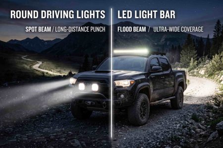
A spot beam concentrates a larger share of a lamp’s output toward a narrower part of the scene. That can make it useful for seeing an access track, field boundary, distant obstacle, or work area ahead of a moving machine. Concentration is the key idea: it does not create extra light from nowhere. It redistributes available light so that one region receives more intensity while adjacent regions receive less.
KC HiLiTES’ pattern guide describes its spot or long-range pattern as a concentrated, tightly focused beam intended for extended visibility, and identifies off-highway, commercial, agricultural, and racing use cases. That is a manufacturer’s description of its product family, not a universal definition or a guarantee that every spot lamp has the same reach. The source is helpful because it distinguishes a spot distribution from the broader flood distribution, but the actual reach still depends on measured intensity, the mounting angle, and the receiving surface.
Spot optics can be useful when the operator has time to look toward the beam center and needs to anticipate a change ahead. Examples include slowly approaching a gate on an unlit private road, identifying the edge of a field before turning, or checking a long stretch of a site perimeter. The beam’s stronger central region can reveal a distant object earlier than a wide lamp with the same total flux, provided that the object lies inside the spot’s useful distribution and the conditions allow adequate contrast.
The limitations follow from that concentration. A narrow pattern can leave nearby ground, side approaches, and equipment edges comparatively dim. If the operator turns the machine or works off-axis, the useful hotspot can move away from the task. A roof-mounted spot can also strike dust, rain, snow, or a reflective hood and send scattered light back toward the operator. These are not reasons to reject spot beams; they are reasons to aim and position them for a defined forward task rather than treating them as universal area lights.
Spot is often a poor one-lamp answer for stationary repair work. A mechanic leaning beside a truck needs to see hands, connectors, fasteners, and nearby surfaces. A tight center hotspot can create a bright patch while leaving the rest of the work area uneven. The same is true when an operator must monitor the full width of an attachment. In those cases, a flood pattern or multiple lamps aimed at separate zones is usually easier to use.
What a flood beam does well
A flood beam distributes light across a broader area, typically trading some central intensity for wider near-field coverage. It is useful when the operator needs to see a surface, a worksite, or equipment around the vehicle rather than one distant point. Reversing, loading, inspecting an attachment, setting up a campsite, and carrying out maintenance are common situations where surrounding visibility can matter more than maximum reach.
KC HiLiTES describes its flood pattern as a broad pattern with substantial horizontal and vertical coverage, suited to work lights and backup lights at shorter distances. As with its spot description, this should be understood as a product-family explanation, not a precise angular specification for every flood lamp. A datasheet, photometric file, or beam diagram is more useful than the word “flood” when exact coverage matters.
Broad coverage can help the operator notice edges and nearby movement that would fall outside a narrow center hotspot. It can also make a work area feel more evenly illuminated when the light is mounted near the task and aimed down. But broad does not automatically mean even. Some flood lamps still have a central peak, a sharp edge, or a pattern that is wider vertically than expected. Optical design, lens shape, reflector geometry, and mounting angle all affect the distribution.
Flood patterns also have limits. They may not provide enough intensity at a long distance for the operator to identify a small object early. A lamp mounted high can spread light across airborne dust, mist, or falling snow; this may increase veiling reflections in the viewing direction. A very broad pattern aimed straight ahead can brighten the foreground so much that a darker distant scene appears less distinct by comparison. Good aim and sensible switching matter as much as the pattern label.
For a stationary task, the right flood pattern should cover the actual working plane without putting a bright source directly in the operator’s eyes. If the surface is below the lamp, a down-and-out aim may reduce wasted light above the task. On a truck, trailer, or machine, use several mounting points when the body or attachment blocks a single lamp’s view. A wide beam cannot illuminate through steel, a cargo load, a raised bucket, or a trailer wall.
The practical starting point is therefore not “flood is always for work” but “flood is a candidate when the task needs a broad nearby zone.” If the operator must identify detail, test the lamp at the real distance and on the actual material. A wet black surface, pale gravel, reflective tape, and a dark tire do not return the same amount of light to the eye. The intended task and the surface matter together.
Where wide flood and combo patterns fit
Some catalogs separate flood from wide flood. Others use overlapping terms, or call a product “scene,” “work,” or “area” lighting. Treat those names as clues. The important question is how the beam spreads in both horizontal and vertical directions. A wide horizontal pattern with controlled vertical spread may cover an attachment without wasting much light above it; a broad pattern in both planes may be better for a low, close, open work zone. Ask for a photometric diagram when the difference affects the job.
A combo pattern attempts to provide a more concentrated forward region together with broader spill. A long light bar may combine different optics across its length, or a single lamp may shape its distribution to include a center hotspot and side fill. Those arrangements can simplify a setup, but they do not remove trade-offs. A combined beam may not reach as far as a dedicated spot at the same input power, and it may not cover the near field as evenly as a dedicated flood. One enclosure also fixes the relationship between its zones: the operator cannot independently aim the center and side portions unless the product is specifically designed to allow that adjustment.
Separate lamps can be more flexible when the vehicle has several useful mounting locations. A forward spot can be aimed toward a distant route, while side and rear floods illuminate the operator’s immediate work area. Each switch can then be used only when its pattern is useful. The cost is more wiring, more mounts, more potential glare, and more installation complexity. A single combo lamp may be easier to install; a distributed set may be easier to tailor. Choose based on the tasks and mounting opportunities rather than the number of pattern names in a listing.
Do not assume that a “combo” label means the beam will be balanced for every mounting height or work speed. If possible, view a beam shot taken under controlled conditions or inspect the manufacturer’s photometric file. A staged photograph with a camera’s exposure changed between images is not a reliable comparison. The camera may make two beams look equally bright even when measured values differ, or make a broad low-intensity spill look more dramatic than it is.
How to read lumen, candela, lux, and beam data
The basic measurements answer different questions. Lumens describe luminous flux: the total visible-light output from the source or lamp under a stated measurement condition. Candela describes luminous intensity in a particular direction. Lux describes illuminance arriving on a surface; one lux equals one lumen per square meter. A beam angle or distribution plot describes how intensity changes across direction. None of these numbers alone describes the complete work scene.
This distinction explains why two lamps with similar lumen totals can look very different at a distance. A narrow optic may place more of its output into a smaller angular region, raising intensity near the center. A broad optic may distribute output over a larger area, producing more coverage but less intensity in any one direction. The first can have more candela in the hotspot; the second can illuminate more nearby surface. The actual product’s measurement should be used when comparing products. A calculation based only on the LED chip’s nominal output omits losses from the lens, reflector, thermal conditions, driver, and power supply.
Lux is useful when tied to a measurement point and surface orientation. In a simplified far-field example, a source with 10,000 candela in the direction of a target would produce 100 lux on a surface perpendicular to the ray at 10 meters, before accounting for atmospheric scattering, obstructions, surface reflection, or other light sources. At 20 meters the idealized value would be 25 lux, because the distance doubled and illuminance from a point source falls with the square of distance. The Australian Government lighting manual explains this inverse-square relationship and the cosine effect when light strikes a surface at an angle. This example illustrates the relationship; it is not a performance claim for any SAEC lamp.
The surface angle matters because a beam that reaches a floor obliquely spreads over a larger patch. A lamp aimed down onto ground can therefore produce less illuminance at the edge of its coverage than the same candela would produce on a perpendicular target. On sloped ground, a loading ramp, or a vertical machine panel, the angle changes again. That is why a catalog beam angle does not tell you the lux on a particular task surface without geometry and intensity data. The Australian Government lighting manual illustrates the inverse-square and cosine relationships for general lighting; those principles explain the measurement geometry here, while the manual is not an automotive lamp regulation.
Beam angle also needs context. Some manufacturers report the angle between points where intensity falls to a defined fraction of its maximum. Others may use a product-specific convention or provide a beam illustration without stating how it was measured. Horizontal width and vertical height are not interchangeable. A nominal “60-degree flood” can hide a very different rectangular shape from another lamp with the same label. When available, use a photometric distribution file, an intensity table, or a clearly scaled beam plot rather than relying on the product name.
| Data item | What it helps answer | What it does not answer by itself |
|---|---|---|
| Lumens | How much visible luminous flux the lamp reports producing | Where that flux lands or how far detail is visible |
| Candela | How intense the lamp is in a stated direction | How wide the useful field is or whether the edge is uniform |
| Lux | How much illuminance reaches a defined point and plane | How a person perceives contrast, color, glare, or task detail |
| Beam angle | How broadly the distribution spreads under the stated convention | Exact lux on a surface without distance, angle, and intensity data |
| Watts | Electrical input under the stated operating condition | Useful light, thermal performance, or beam quality |
| “Reach” claim | A vendor’s stated visibility or detection distance | A standardized guarantee unless the test method and threshold are given |
When a product page offers only a lumen number and a beam label, be honest about the limits of the comparison. You can still screen for likely use, housing size, voltage, and mounting options, but you cannot calculate exact task illuminance from those fields alone. Request a technical sheet if the decision depends on a particular distance or a minimum light level. If the manufacturer does not provide that information, compare only under a repeatable test or select a product with clearer documentation.
Choose a pattern for the task
Different machine jobs create different distributions of useful viewing targets. A tractor preparing to reverse toward an implement needs a broad area behind it. A loader crossing an unlit field may need longer forward preview between work zones. A utility truck repairing a roadside sign needs light on the hands and equipment without dazzling traffic or reflecting into the windshield. The following examples are starting points, not universal prescriptions; the final choice depends on lamp data, mounting, the vehicle manual, and the site’s work-safety requirements.
Reversing and hitching
For backing, trailer alignment, or connecting an implement, begin with a flood or wide-flood pattern aimed at the ground, hitch, and adjacent area. The operator needs side-to-side context to judge alignment and detect people or obstacles beside the vehicle. A spot beam can create a bright point behind the machine while leaving the outer corners dark. If the vehicle is long or a trailer blocks the view, separate lamps at rear corners can reduce shadowing better than one high central lamp.
The appropriate placement should not cause the bright lamp to appear in a mirror or wash out a backup camera. Test from the driver’s actual eye position and check camera exposure, mirror reflection, and any manufacturer guidance for auxiliary reverse lights. If the vehicle is used on public roads, verify local rules for lamp activation, color, and use. This guide does not establish road legality.
Implements and attachment work
An implement can be the most important target in the scene. Rear-facing flood lights on a tractor or equipment cab can illuminate the hitch and the area where a worker may need to inspect a connection. Side-facing lights can help when the attachment extends beyond the vehicle’s body. A very wide pattern may be useful for an attachment that spans a broad width, while a narrower flood may waste less light on irrelevant areas.
An elevated mount is not automatically better. The attachment itself can cast a shadow, and a lamp aimed across dust or spray may produce a bright cloud in front of the operator. Position the lamp so that its beam reaches the working surface at a useful angle. If the task requires someone to approach the moving machinery, lighting does not replace lockout, visibility clothing, a spotter, or the equipment’s safety procedures.
Inspection and service work
Close inspection usually benefits from an even flood pattern, supplemented by a portable task light when a specific connector, fastener, or label must be examined. A fixed lamp can provide general area visibility, but the operator’s body and tools can block it. Two lower-output lamps from different directions can sometimes reduce harsh shadows more effectively than one higher-output lamp aimed directly at the task.
Where color differences matter, such as identifying fluid condition, wire insulation, paint, or a warning indicator, color appearance becomes another selection factor. A work lamp’s correlated color temperature and color-rendering information may help describe its light, but those measures do not define the beam geometry. Keep the two decisions separate: first choose a useful distribution, then evaluate color, glare, and task-specific visibility under representative conditions.
Field travel and site perimeter checks
When an operator travels between work zones, a forward spot or driving pattern can help identify route changes ahead. For low-speed field work, a moderate forward pattern may be enough; higher travel speeds require more stopping distance and more preview, but a work lamp is not automatically a suitable road-driving lamp. Use the vehicle’s approved headlamps and follow road rules whenever the route is public. On a private worksite, still aim auxiliary lights to avoid dazzling other operators.
For perimeter inspection, the useful beam may need to illuminate a fence line or field edge while the vehicle is stationary. A spot can reveal a distant gate, while a flood can reveal the ground immediately beside the cab. A rotating searchlight or a separately aimed lamp may suit an inspection task better than a fixed bar. Choose a beam that reaches the line of interest without forcing the operator to stare into the source or leave dark areas around the vehicle.
Mobile service and roadside maintenance
A service body often needs several distinct areas: the ground beside the truck, the open compartment, the repair surface, and the traffic-facing side. A broad flood can support general setup, while a task light placed close to the work may provide more controlled detail. If equipment is used near moving traffic, follow the employer’s traffic-control plan and local work-zone requirements. A lamp beam cannot replace warning devices, barriers, high-visibility clothing, or a safe parking position.
The optical choice should also consider where a person will stand. A lamp pointed outward from the side of a truck can illuminate a repair area; the same lamp may shine into the eyes of a colleague approaching from that direction. Rotatable brackets can help aim a scene light after parking. Operators should understand each switch and avoid energizing high-output work lamps where others can be dazzled.
Forklift and warehouse loading
Forklifts generally work at low speeds in spaces where nearby edges, people, rack faces, loads, and floor markings matter. Flood patterns can provide useful ambient and close-range visibility, although reflections from glossy wrap, metal, or polished floors may create glare. Position lights so that a load or mast does not block the beam. Where a facility has a formal lux requirement, measure at the working plane and use the facility’s engineering criteria.
A spot beam may help inspect a long aisle or a specific distant point, but it is rarely a substitute for a designed warehouse lighting system. Mobile work lights create shadows that move with the forklift and can alter other operators’ visibility. Coordinate any added lighting with the site’s safety manager and ensure it does not conflict with pedestrian warning systems, cameras, or the original lamp arrangement.
Excavators, loaders, and skid steers
These machines change shape as booms, buckets, arms, and attachments move. One fixed lamp can be hidden at one position and create glare at another. Place broad beams to cover the immediate work zone from more than one useful direction where the machine’s design allows it. A forward spot can support travel between work areas; a separate flood can illuminate the bucket or attachment. Check the beam at the full range of normal equipment movement.
Mounting a lamp on an arm or attachment changes the wiring and durability requirements. Moving harnesses need protected routing, strain relief, bend allowance, and compatibility with the machine’s manufacturer guidance. A work lamp that is optically ideal may still be a poor purchase if there is no safe mounting location or the cable would flex, pinch, or abrade.
Match the beam to the mounting position
The lamp’s location changes the distance, angle, shadow, and obstruction between the optic and the target. Evaluate the complete path from lamp to work surface. A roof-mounted lamp begins higher and can project farther before terrain interrupts the beam. A low-mounted lamp may better fill the near ground but can be blocked by a bumper, wheel, attachment, or dirt accumulation. A side lamp should cover the area operators actually use when they approach the machine, and a rear lamp should illuminate the reversing or servicing zone without reflecting harshly in mirrors.
Mount height also changes glare. A source close to the operator’s line of sight may feel uncomfortable even when it illuminates the ground effectively. A source mounted above eye height can still reflect from the hood, windshield, dust, wet pavement, or a metal surface. For equipment with an enclosed cab, inspect from the normal seated position with windows and mirrors in their typical condition. For open cabs, account for direct view of the lamp and reflected light from tools or attachment surfaces.
Aim each lamp after installation under realistic working conditions. Park on a level area, set the machine at its common operating height, and position the attachment as it will be used. Check for a bright patch that is too close, a dark gap at the target, a side shadow, or reflections toward the operator. A beam that looks wide when the vehicle is stationary can become poorly aligned when the suspension is loaded or an implement is raised.
For a moving work vehicle, keep forward lighting separate from area lighting in both aim and operation. A scene lamp generally serves a stationary or slow work zone. A forward-facing lamp may be used while moving only where it is permitted and does not conflict with road regulations, the vehicle manual, or site policy. Dedicated road-approved lighting follows separate photometric and installation requirements. The classification depends on the lamp and jurisdiction; a generic work-light label does not establish approval.

Before choosing a bracket, check the physical envelope: lamp dimensions, mounting foot, adjuster range, cable exit direction, connector clearance, and room to reach fasteners. Check that the lamp will not obstruct a camera, radar sensor, cooling inlet, winch line, service panel, or manufacturer-identified keep-out area. Verify that the mounting surface can carry the lamp under vibration. Use the prescribed hardware and torque for the mounting system; do not rely on an improvised bracket that can rotate or fatigue.
Compare work lights fairly
A useful comparison begins with lamps that serve the same task and can be mounted in comparable positions. A fair spot vs flood LED work lights comparison uses the same distance, target height, surface, supply voltage, ambient conditions, camera exposure, and warm-up period. If the products have different mounting heights or orientations, record the difference rather than hiding it. A comparison photograph alone can illustrate a pattern; it cannot establish an exact lux level unless the test includes calibrated measurements and a stated method.
Read the product sheet for the measurement condition behind each number. A maker may report LED chip lumens, theoretical output, measured lamp lumens, peak candela, or lux at a distance. Those measures are not interchangeable. Compare like with like. If one lamp lists input power and another lists emitter power, that is not an equal electrical comparison. If one chart shows peak center intensity and the other shows average work-zone illuminance, the numbers answer different questions.
| Comparison question | What to record | Why it matters |
|---|---|---|
| What is the task? | Distance, target size, surface, movement speed | Defines the useful zone instead of an abstract brightness goal |
| What is the distribution? | Horizontal and vertical plots or a scaled beam diagram | Shows where the light is concentrated and where gaps may remain |
| What is the output metric? | Measured lamp lumens, candela, or lux with conditions | Prevents a chip claim from being compared with a surface reading |
| How is it powered? | Rated voltage, current, input watts, and test voltage | Reveals whether the comparison used the same electrical conditions |
| How is it installed? | Mounting height, bracket, aim, and cable route | Connects laboratory data to the real machine geometry |
| How does it hold up? | IP rating scope, vibration/impact data, temperature range | Helps determine whether the lamp suits the actual environment |
| What approval applies? | Markings and documentation for the specific jurisdiction/use | Separates work lighting from road-use approval |
Use the manufacturer’s optical diagrams as evidence about the intended design, then look for independent photometric testing if the application needs a defensible performance result. A product photograph may show the beam at one exposure and one distance. It can help illustrate a pattern, yet automatic camera exposure, editing, haze, wall reflectance, and the position of the camera can change the appearance. Treat promotional beam shots as visual aids, not calibrated measurements.
Pay attention to output at operating temperature. LED performance can vary with temperature and electrical conditions. A short test from a cold lamp may not represent an extended shift in a warm enclosure. Compare results after both products have reached a stable operating state, follow any manufacturer test instructions, and note when the result was recorded. Do not open sealed lighting products to inspect an optic or modify a thermal path unless the manufacturer specifically authorizes that service.
It is also helpful to compare mounting accessories and harnesses as part of the system. A lamp that includes the correct bracket, sealed connectors, and a supported cable route may reduce installation uncertainty. Conversely, a high-output fixture can draw more current than an existing auxiliary circuit can supply. Confirm the wiring and fuse requirements for the exact product and vehicle rather than choosing from wattage alone. A photometrically suitable lamp still needs a sound electrical installation.
Test coverage before you commit
A simple field test can reveal whether a candidate beam reaches the task and covers its useful width. It should be repeatable and safe. Use a level, controlled location that is not open to public traffic, follow the equipment manual, and keep people out of the beam path. Do not look directly into a powered lamp. If electrical measurements or mounting work are outside your training, ask a qualified installer or lighting technician to do them.
Start by marking the task plane. For a ground task, choose the working surface and mark points at the center, the expected edges, and one or more distances. For a vertical target, mark heights as well as horizontal positions. If comparison requires a particular visibility threshold, obtain that target from a qualified lighting plan or applicable workplace standard; do not invent a threshold from a product page. A lux meter can record illuminance at each point when its range and calibration are appropriate.
Keep the geometry consistent. Place the lamp at the intended mounting height, use the same aim, and set the target surface at a known distance. Record where the meter is held and whether its sensor plane faces the lamp or the task surface. The Australian Government lighting manual explains why distance and surface angle affect measured illuminance; a reading taken at one point cannot describe every part of a beam. Take a grid of readings when coverage uniformity matters.
Measure the spot and flood candidates separately, then test any combination with the lamps aimed as they would be used. Write down the voltage at the lamp if a qualified person can measure it safely, along with operating temperature, time after switch-on, and environmental conditions. Keep the same background light and surface whenever possible. If the surroundings change, repeat the comparison rather than assuming that the earlier readings still apply.
A practical record sheet can include these fields:
- product make/model and stated beam type;
- supply voltage and current, if measured safely;
- mounting height, aim, and distance to the target plane;
- location and orientation of every lux-meter reading;
- time after switch-on and ambient temperature;
- weather, dust, moisture, and surface condition;
- operator notes about shadows, reflections, contrast, and glare.
The meter and the operator’s observation complement one another. A high center reading may coexist with dark edges; a visually smooth scene may still fail to show a low-contrast obstacle. A meter does not assess whether the operator can identify a color or recognize a moving person in time. Pair measurement with a task check that uses representative objects and a safe procedure. Keep the human observer in a position that avoids direct glare and record where the observer stood.
Consider the following example: a maintenance truck carries out two tasks after dark. The first is inspecting a connector beside the rear wheel while parked. The second is slowly moving along a private service lane. A broad side flood can illuminate the repair zone; a forward spot can provide more preview along the lane. One lamp is unlikely to do both jobs equally well. The operator can turn off the forward lamp while working close to the truck and use the side flood only when it is safe to do so. The final system should still follow the vehicle maker’s electrical guidance and the worksite’s lighting rules.
Build a practical multi-light setup
When a machine has several jobs, design the lighting as a set of zones. A useful layout may include a forward travel zone, a near-ground zone, side access zones, an attachment zone, and a service zone. Each zone has a task, a mounting location, a target distance, and a preferred distribution. This makes it easier to decide whether one lamp can serve two tasks or whether a second location is needed. It also gives an installer a clear aim target instead of the vague instruction to “make it brighter.”
Think through the operator’s work cycle. A loader might travel across a site, park, lower a bucket, load material, reverse, and reposition. The best forward pattern during travel may not be the best pattern when the machine is parked and the operator checks the bucket. A system with independently controlled front, side, and rear lamps allows the operator to use the smallest useful set at each step. That can reduce unnecessary glare and make it clear which light is intended for each task.
Controls should be intuitive. Label switches in the cab in a way the operator can understand, and keep the controls consistent with the vehicle’s approved switching and safety design. A high-output lamp should not unexpectedly turn on with a function that places it in the view of another worker or a road user. If multiple operators use the same machine, train them on the lighting zones, the conditions for use, and how to report a failed lamp or loose bracket.
Avoid aiming every lamp in the same direction simply because the brackets are easy to reach. Overlapping beams can create a very bright patch while still leaving dark edges. Overlap may be useful for continuity, but each beam should have a reason to occupy that area. A rear flood and a side flood can create a more complete work envelope than two rear lamps with identical aim. A spot and a flood may complement one another if the central long-range zone and near side zone both matter.
The machine’s original lights remain part of the system. Auxiliary lamps should complement the factory illumination and should not obstruct, replace, or interfere with the equipment’s required lighting. If the vehicle uses cameras, radar, telematics antennas, or automatic headlamp systems, check the manufacturer’s instructions before adding equipment near those parts. The accessory lamp’s position, current draw, and electromagnetic behavior can matter even when its beam appears ideal.
For a general view of the way auxiliary lamp types differ, see SAEC’s LED light bar versus driving light guide. That article addresses a different comparison from spot versus flood work lamps. The spot vs flood LED work lights decision still depends on the equipment, work cycle, and measurement point. Browse the industrial LED work-light category for examples of fixtures intended for work-area lighting; check the exact product page for its optical options, electrical data, dimensions, and installation instructions.
Check electrical and environmental fit
The beam pattern is only one part of the purchase. Confirm the lamp’s voltage range, current draw, connector, polarity, mounting hardware, and harness requirements for the exact vehicle or machine. A nominal wattage does not say whether an existing switch, circuit, or connector can support the lamp. Follow the manufacturer’s wiring instructions and use correctly rated fusing, conductors, protection, and switching. If the vehicle has a monitored lighting circuit or a sensitive electronic system, consult the vehicle maker or a qualified installer before making changes.
Keep the cable route in view while comparing products. The lead should reach the planned connection without crossing a hot exhaust component, sharp edge, steering joint, moving arm, pinch point, or service path. Allow the movement and bend radius required by the equipment manufacturer. Protect connectors from water and dirt in accordance with their design. A lamp that cannot be wired and serviced safely in the available location is not a suitable choice for that position.
Environmental ratings also need careful reading. An IP code describes protection under specified test conditions; it does not by itself demonstrate resistance to every cleaning method, chemical, salt exposure, vibration level, impact, or temperature cycle. Check the test scope and the exact product documentation. Do not infer an unlisted capability from the use of phrases such as “waterproof,” “heavy duty,” or “military grade.” For equipment exposed to washdown, dust, mud, or continuous vibration, ask the manufacturer for the relevant test evidence and mounting conditions.
Consider heat, service access, and dirt accumulation. A compact lamp may fit behind a grille but be difficult to clean or cool. A position exposed to mud can obscure the lens and reduce useful output even when the LEDs remain functional. A large front face can collect debris; a bracket can trap material or water; an inaccessible connector can make routine service difficult. Check whether the lamp’s orientation is restricted, whether the housing needs open airflow, and how a technician will inspect or replace it.
The lens and housing need to withstand the real job. Equipment can experience vibration, shock, and repeated thermal changes. Verify that the manufacturer has documentation relevant to the intended application, and inspect the lens, fasteners, brackets, and seals during regular equipment maintenance. Do not treat a beam label as evidence of durability. Optical design, mechanical construction, electrical protection, and environmental testing are separate product attributes.
Color temperature and color rendition may matter to some tasks. A cooler-looking lamp is not automatically more useful, and a high color-rendering score does not guarantee a good beam. For color-coded wires, fluid inspection, or reading markings, judge the actual target under the lamp and compare like-for-like products with their color data disclosed. Avoid using a white work light as the sole basis for color-critical inspection; follow the relevant professional procedure if the task has a required color standard.
If vehicle electrical compatibility is a concern, see SAEC’s published LED headlight flicker troubleshooting guide for a separate discussion of vehicle lighting circuits. That article does not certify a particular work light or vehicle fitment. The LED pod category is another product family; its inclusion here is for browsing only, and the product’s intended use and specifications must be checked individually.
Seven-point buyer checklist
Use this checklist before ordering. A spot vs flood LED work lights decision should stay tied to the real job and record the information a supplier or installer may need.
- Describe the target. Write down what the operator must see, how far away it is, how wide the area is, and whether the machine is moving or stationary.
- Choose a provisional distribution. Select spot for a defined forward-distance task, flood for a broad nearby zone, and wide flood or multiple lamps when the width is especially important. Treat “combo” as a candidate whose actual distribution still needs checking.
- Request usable photometric data. Look for a beam plot, candela table, or lux readings tied to a distance, supply condition, and method. Identify whether lumen figures describe the LED source or the finished lamp.
- Map the mount. Check aim range, height, obstructions, cable exit, service access, camera and sensor clearance, and the expected movement of any attachment.
- Confirm the electrical system. Match the voltage range, rated current, harness, connector, fusing, switch, and manufacturer installation instructions to the specific vehicle.
- Check durability evidence. Review the product’s dust and water test scope, temperature range, vibration or impact evidence, and cleaning limitations for the actual working environment.
- Plan a safe field check. Decide how coverage and glare will be inspected after installation, who will do it, what task plane will be measured, and how results will be recorded.
The checklist can also expose a missing specification. If an operator cannot say what distance matters, a long-range number on a product page will not solve the selection problem. If the seller cannot supply the mounting dimensions or wiring requirements, resolve those details before purchase. If the job depends on a workplace illumination threshold, consult the applicable safety or lighting professional rather than guessing from lumen totals.
A simple selection matrix
| Work situation | Beam to evaluate first | Useful placement | Important check |
|---|---|---|---|
| Backing or hitching | Flood or wide flood | Rear corners or elevated rear work-light mounts | Camera, mirror reflections, people at the sides |
| Inspecting a close repair | Flood plus portable task light if needed | Side or service-area mount | Tool shadows, connector visibility, operator glare |
| Monitoring a wide implement | Wide flood or multiple floods | Rear and side positions | Attachment shadow, full operating movement |
| Moving slowly along a private lane | Spot or a measured forward distribution | Forward-facing position | Useful preview, route rules, glare to others |
| Lighting a loading zone | Flood | High side/rear position aimed at work plane | Reflections from wrap, metal, or wet surfaces |
| Checking a distant site boundary | Spot | Forward-facing or adjustable inspection mount | Whether the target stays within the beam during turns |
| Working around several sides of a machine | Separate flood zones, optionally a forward spot | Front, side, and rear mounts | Independent switching and complete shadow check |
The matrix suggests a first test, not an automatic product answer. A machine’s body, task surface, local rules, and operator position can change the result. A slow, compact forklift with high-reflectance surfaces may need a different distribution from a large loader working on rough, dark ground. Confirm the exact installation with the equipment manual and a field test.
Frequently asked questions
Are spot or flood LED work lights brighter?
Neither pattern is inherently brighter. Spot vs flood LED work lights are distinguished by distribution, so a spot usually concentrates more of its output in a central region while a flood spreads it over a wider area. The spot’s center may appear more intense, while the flood may reveal more of the nearby scene. Compare a like-for-like photometric metric at the relevant point and distance.
Is a flood beam better for work lights?
Flood is a practical starting point for broad, nearby tasks such as reversing, attachment monitoring, or lighting a service area. The target distance, coverage width, mounting height, and operator’s view still matter. A work vehicle that travels between sites may also need a separately aimed forward beam, subject to the vehicle maker’s instructions and local rules.
When should I choose a spot beam work light?
Choose a spot candidate when the operator must inspect a defined area farther ahead, such as a field boundary or private-site access lane. Check the actual distribution and mounting angle. A spot pattern can leave near and side zones dim, so it may need companion flood lamps if the work also includes reversing, repairs, or attachment monitoring.
What is the difference between flood and wide flood?
The terms are not used consistently by every manufacturer. Wide flood generally signals broader coverage, especially near the machine, but the name alone does not define an exact angle. Compare horizontal and vertical distribution data, beam diagrams, or a controlled field test before treating two products as equivalent.
Does a higher lumen number mean a light reaches farther?
Not by itself. Lumens describe total luminous flux; reach also depends on how the optic distributes that flux and on intensity in the direction of the target. A narrow beam can have higher center intensity than a broad beam with a similar lumen total. Look for candela, a measured lux value at a stated distance, and the test conditions.
Can one combo beam replace separate spot and flood lamps?
It may cover multiple needs in a simpler package, but a combo design still has a particular distribution, mounting direction, and balance between center and side coverage. Separate lamps can be independently aimed and switched. Compare the product’s beam plot with the actual work zones before deciding that either layout is enough.
How do I compare two beam patterns at home or on site?
Use a safe, controlled location and identical geometry, voltage conditions, target surface, and camera exposure. A lux meter can record readings on a grid at defined distances and angles. Never stare into a powered lamp, and use a qualified installer for electrical or mounting work outside your training. Treat photographs as illustrations unless their measurement method is documented.
Can a work light be used as a driving light on public roads?
Do not assume so. Road-use lighting can have separate photometric, marking, mounting, color, and switching requirements. Check the exact lamp documentation and the rules for the jurisdiction and vehicle. A work-light category or a spot beam label does not prove that a lamp is approved for road use.
Should I mount every work light as high as possible?
No single mounting height suits every task. A higher lamp can project farther over nearby obstructions, while a lower lamp can fill a close work surface. Height also changes glare, reflections, shadows, and how much airborne dust is illuminated. Use a structurally sound location, preserve service access, and check the beam from the operator’s normal position.
What should I ask a seller before ordering?
Ask for the finished lamp’s optical distribution, the meaning and test condition of the lumen claim, supply voltage and current, mounting dimensions, harness requirements, environmental test scope, and any applicable approval documents. Describe your target distance and mounting location so the seller can answer against a real use case rather than recommend the largest output number.
Sources
- KC HiLiTES: What are the differences between the types of light patterns? — manufacturer descriptions of spot, driving, spread, fog, and flood patterns and typical uses.
- Australian Government: Lighting Manual — general photometric explanation of illuminance, inverse-square behavior, and the cosine law; it is not an automotive lighting regulation.
- TUFF PLUS: Flood Beam vs Spot Beam — LED Work Light Guide — current commercial industry example for work-light tasks and mounting positions; not independent performance testing.
- U.S. Department of Energy: LED Basics — background on LED systems and light-source measurements.
Editorial note: Prepared by the SAEC Lighting Engineering Team, Foshan. Product specifications and installation requirements vary by model. Verify the current manufacturer documentation and the rules that apply to your vehicle and worksite before installation. Last checked October 12, 2026.
 by


