


On this page
A curved vs straight LED light bar decision starts with the vehicle’s mounting surface and the light’s independently specified optics. Curvature can help a bar follow a windshield, bumper, or roofline and can change how angled modules point outward, but it does not by itself prove wider usable illumination, greater reach, or better performance. Measure the available space, check the maker’s beam data, and confirm that the mounts let you aim the finished assembly safely.
The most useful comparison is not a style contest between two silhouettes. A bar is a package of housing, emitters, reflectors or lenses, wiring, brackets, and an installation angle. Shape affects packaging and may affect the directions individual lamps face; optics control how each lamp distributes light; aiming controls where the distribution lands. Those factors can be designed together, but they answer different questions. This guide uses a buyer’s workflow to keep them separate and show when an arc, a straight profile, or a configurable modular assembly is the more practical fit.
Choose by the mounting surface first
Start by identifying the exact mounting surface, not by choosing a curve from a product photograph. A windshield header, roof rack, bumper opening, grille recess, roll bar, and upper cab each have a different width, radius, support structure, and clearance envelope. A curved bar may follow a broad front contour more closely on one vehicle; a straight bar may sit flush in a flat bumper aperture. Either profile can look wrong or create a difficult installation when the bracket spacing, depth, or arc does not match the vehicle.
Measure the usable area between obstructions. Record the width between mounting points, the depth available behind the grille or above the bumper, the height beneath a roof rack, and the distance to the windshield, hood, body panels, sensors, and movable accessories. Measure the surface itself as well as the apparent opening. A decorative bumper cover can hide a structural beam set farther back, while a grille may leave room for a lamp body but not for its rear connector or cable bend.
Use a cardboard profile, paper template, or the manufacturer’s dimensional drawing to model the full assembly. Include the end caps, side brackets, adjusters, wire exit, connectors, and any space needed to tighten fasteners. A bar that is 40 inches long at its front face may require more than 40 inches of clear width once its feet and side brackets are fitted. A curve may alter the overall width at the front edge while bringing the center or ends closer to the body, depending on the orientation. Never infer the complete envelope from the advertised nominal length alone.
Check the mounting plane from several viewpoints. Look at the front of the vehicle with the hood closed, then inspect from above and from the side. Consider whether the lamp will sit behind a grille, above a bumper, or forward of a body panel. The face should have an unobstructed view in its intended direction, and the housing should not collide with a hood, winch rope, recovery point, grille shutter, windshield wiper, roof accessory, or service panel. On a vehicle with radar, camera, parking sensor, adaptive cruise control, or active grille equipment, the manufacturer’s location restrictions take priority over a universal accessory guide.
For a surface that is visibly arched from side to side, compare how the bar’s arc relates to the body line rather than assuming the product will conform perfectly. A gentle curve may visually align with a bumper, but the end-to-end radius can still differ enough to leave uneven gaps or point the ends away from the target. A flat surface can often accept either shape if the bracket design allows it, but a curved housing may project farther forward at its center or ends. These are fitment questions that a measurement drawing can answer; brand language such as “universal” cannot.
Installation location also determines exposure and usability. A low bumper position is often easier to reach and can protect the light behind the vehicle’s profile, but it is more exposed to rocks, mud, water, and snow. A roofline position can provide a higher viewpoint and keep the bar clear of some front obstructions, but it may increase wind exposure, roof load, glare from weather, and difficulty in servicing the lamp. A grille opening may offer a clean appearance while limiting airflow or access. Compare the curve and straight options only after deciding which location the vehicle and task can support.
Use product-specific fitment evidence where possible. A vehicle-specific kit should identify the model years, trim, mounting point, included hardware, and any exclusions. A universal bar should be treated as a lamp that still needs a compatible mount; “universal” does not mean it fits every bumper, can be safely attached to any thin panel, or meets every local road-use rule. A bracket listing can show whether one bar shape is accepted at a particular location, but it does not certify a different vehicle or prove that the structure is strong enough for that vehicle’s vibration and loads.
When the available space is irregular, choose a modular or adjustable arrangement only if its instructions specify the permitted arc, module count, fasteners, and aiming range. Baja Designs describes its XL Linkable system as configurable to a straight or arced layout and provides a system-specific diagram comparing 44-degree straight spread with 64-degree arced spread. That is useful evidence for that modular assembly, not a universal rule that any curved bar creates a particular beam angle. KC HiLiTES similarly documents a Profile system that can be set straight or curved by changing a linker bracket. The existence of configurable designs reinforces the buyer’s first task: verify the exact assembly and its approved configuration.
What the curve changes—and what it does not
A curved bar places its light modules along an arc instead of one straight line. Depending on the module design and orientation, the outer lights may point slightly toward the sides. When that outward angle is part of the optical and mechanical design, the combined pattern can cover a wider horizontal span near the vehicle or around a bend. The amount of change depends on the radius, the number and spacing of modules, the module’s own optics, and the way the unit is aimed.
The curve also changes the physical outline. A bar with a profile that follows a vehicle’s fascia or windshield line may look more integrated, leave less of a visible gap at the ends, or sit inside a particular bumper opening. Those are valid purchase criteria when the actual clearance and mounting points have been checked. Appearance alone, however, does not show what lands on the road or trail. A curved product can still use narrow spot optics, and a straight product can still use wide-cornering optics, a combination of reflector types, or modules mounted at different angles.
There is no optical law that says a curved housing must provide more total light, a longer reach, a better-behaved beam, or more useful coverage in every direction. A curve can redistribute where modules point; it does not create additional luminous flux. If the outer modules turn outward, their intensity along the vehicle centerline may differ from a comparable straight configuration, while lateral illumination may increase. Whether that trade improves the driver’s view depends on the target, installation position, roadway, surface reflectance, and beam pattern. A wider illuminated footprint is not automatically safer or more useful if it leaves insufficient intensity where the driver needs forward contrast.
Manufacturers describe some curved products as providing a wider field. Baja Designs uses that language for its OnX6+ Arc product, while also listing Spot, Driving/Combo, and Wide Cornering pattern options separately. The same product family identifies curved shape and optical pattern as different attributes. That makes its page a good example of why a buyer should inspect the exact configuration instead of reducing a complex product to “curve equals flood.” The manufacturer’s claim can be reported as its description of that product; it should not be generalized to every curved light bar or treated as a third-party comparative measurement.
The manufacturer’s own pattern diagram can be informative if it states the configuration and measurement conditions. The Baja Designs XL Linkable installation instructions compare a straight setup labelled 44 degrees with an arced setup labelled 64 degrees. Those numbers apply to the depicted eight-light modular arrangement. They do not establish that every arced light bar adds 20 degrees, that every point across that span reaches the same illuminance, or that the stated angle is a regulated beam boundary. The diagram answers a narrow configuration question and should be read within that limit.
The word “curved” can also mean more than one thing. It can describe a single continuous housing bent into an arc, an assembly made from straight modules joined at angles, a curved lens or reflector arrangement inside a straight exterior housing, or a curved product body whose emitters still point parallel to the vehicle axis. Those designs do not produce identical geometry. A buyer should ask what physically curves: the outer housing, the module centers, the optical axes, or several of those parts together.
Another practical effect is how a curved profile relates to the vehicle’s own angles. If the lamp’s outer modules are tilted away from center, their near-field patches may reach the shoulders of a trail earlier as the vehicle turns. If the bar sits high or far back, the same outward aim may put more light into nearby vegetation, signs, snowbanks, or barriers. The interaction is not inherently beneficial or harmful. It is a reason to confirm where the light goes from the actual mounting position rather than assuming that a beam spread diagram at a test distance guarantees the same experience on a particular vehicle.
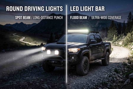
Straight bars have their own optical choices. A straight face may make it simpler to mount multiple independent pods in a horizontal line, or to align the unit across a flat bumper. Some straight bars use spot reflectors in the center and wider optics toward the ends; some allow buyers to choose among different beam configurations; others use one repeated optic throughout. The exterior line alone does not reveal the distribution. A straight product can produce broad coverage, and a curved product can concentrate light.
The most accurate buyer’s rule is therefore conditional: curvature is relevant to vehicle contour, assembly geometry, and the direction of individual modules; the lamp’s optics and aim determine the distribution that matters for seeing. Ask for the exact product’s horizontal and vertical beam information, an iso-lux plot or other photometric report where available, and the mounting assumptions behind that information. If the seller offers only the shape label and lumen total, the available evidence may be insufficient to compare the patterns fairly.
For the curved vs straight LED light bar decision, compare published beam data as carefully as the physical arc. If distribution evidence is unavailable, record that as an unknown rather than assuming one profile wins.
Beam pattern is a separate choice
A beam pattern is produced by the optical system: emitters, reflectors, lenses, shields, and their alignment. “Spot,” “driving,” “combo,” “flood,” and “wide cornering” are product categories that vary among manufacturers, so the label should be treated as a starting point rather than a complete photometric specification. Compare a curve and a straight bar with the same named pattern only if the maker confirms that the two products use comparable optics and operating modes.
The target task decides which distribution is appropriate. A long, narrow pattern may place more intensity down the centerline at distance. A broad horizontal pattern may help with nearby shoulders or work areas. A combination pattern may pair a central long-range region with lateral coverage. A wide cornering optic may prioritize light to the sides. None of these labels alone says that the device is approved for public-road use, that it can be used as a headlamp, or that it should be switched on around other road users. Check the product’s intended-use statement and the rules for the jurisdiction and installation.
Do not use lumen totals as a substitute for distribution data. Lumens describe luminous flux emitted by a source or luminaire under a defined measurement method; they do not say how much light reaches a particular point ahead of the vehicle. A high total flux can be spread across a wide area or concentrated more strongly within a narrower region. A product’s “effective lumens,” raw LED output, or theoretical chip values may not be measured in the same way as complete-fixture output. When two products advertise different numbers, first establish what was measured and whether the values refer to the lamp, the LED package, or a supplier estimate.
Candela and lux help answer different questions. Candela expresses luminous intensity in a direction. Lux measures illuminance at a surface or point. If a manufacturer gives lux at a stated distance and angle, compare the conditions and the measurement point; a single central lux value does not describe the entire width of the beam. A beam chart, iso-lux map, or ECE/SAE test plot, if available and applicable, can show how the distribution changes across horizontal and vertical angles. It is stronger evidence for coverage than a stylized photo of a beam on a dark trail.
Horizontal and vertical distribution should both be considered. A wide horizontal pattern can help reveal the edge of a ditch, but a vertically tall pattern may put more light into signs, dust, tree branches, or an oncoming driver’s sightline. A low, carefully aimed fixture behaves differently from the same lamp mounted high on a roof. A curved housing may make some modules point sideways, but the vertical cutoff, hotspot shape, and glare potential still depend on the optics and aim.
Use the actual pattern options listed for the exact product. Baja Designs’ OnX6+ Arc listing, for example, lists Spot, Driving/Combo, and Wide Cornering selections for the curved bar. The selectable options show that a curved housing is not one single optical pattern. A different product may not offer the same choice. KC HiLiTES’ modular Profile bar specifies its own panoramic, tall beam description. These examples demonstrate how two products with different descriptions must be compared using their exact datasheets rather than the broad word “curved.”
If beam data is unavailable, request it before treating two bars as equivalent. Ask the supplier for a datasheet that states the measurement method, the complete fixture configuration, operating voltage or test condition where relevant, and a distribution chart. If the maker cannot provide photometry, record that as a comparison limit. A buyer can still choose based on fitment, return policy, and a real installation test, but should not convert a marketing description into a quantitative claim.
Finally, choose auxiliary lighting for the context in which it will be operated. A light that is useful off-road may be unsuitable or restricted on public roads. Some systems have separate work, driving, or position-light functions; others include colored auxiliary accents. Wiring methods, switching, aim, and permitted use can vary by product and location. Read the instructions and applicable local rules before installation. Do not connect a high-output bar into factory headlamp wiring or assume a curve makes an auxiliary lamp road legal.
Measure the vehicle before ordering
The advertised length usually refers to a nominal product dimension, not necessarily the widest point of the assembled installation. Product drawings may show the overall width across the lens, width between brackets, center-to-center bracket spacing, housing depth, and mounting-foot position separately. Use the drawing for the exact size, SKU, and configuration you plan to buy. A photo can distort dimensions through perspective, and different versions within one product family may use different end caps or brackets.
Measure the usable span at the intended height. A bumper may narrow toward the grille, a windshield may have a different arc at its top edge than at the hood, and a roof rack may have crossbars at positions that do not match the light’s feet. Record the shape and distance between the proposed mounting surfaces. If the surface is curved, measure at the plane where the brackets will sit, not across a body panel several inches forward. A string, flexible tape, paper template, or cardboard arc can reveal whether a bar’s center and ends will clear the vehicle.
Check the cross-section as well as the width. A tall dual-row lamp may fit the opening by width but hit a grille shutter, radiator support, hood latch, camera bracket, or wiring loom behind it. A slim straight bar can sometimes fit a narrow horizontal slot where a deep curved model cannot. Conversely, a curved bar may extend farther from the body at one point and foul a bumper cover or winch fairlead. Use actual product depth and bracket dimensions to check the full envelope.
Measure the clearance needed to install and service the bar, not only to place it. A tool must reach each fastener. A connector must be unplugged without removing unrelated components. The cable must have a protected route with a bend radius allowed by the wire and connector maker. The lamp may need to slide or pivot during adjustment. If the product includes an adjustable bracket, include its maximum travel in the clearance check so the housing can be aimed without striking the hood, grille, or roof rack.
Do not rely on a vehicle’s nominal width or a competitor’s fitment photo. Model year, trim, bumper package, body repair, aftermarket bumper, winch, brush guard, sensor package, roof rack, and regional equipment can change the available space. A photograph of a similar model may show a different fascia or bracket. Confirm the mounting point using the vehicle maker’s service information and the light maker’s current fitment chart. If no vehicle-specific guide exists, treat the installation as a custom fitment and assess the structure and clearance directly.
For a curved bar, ask for the arc radius or a full-size profile if the outer geometry matters. Some sellers describe only a “curved” shape; that word does not tell you how pronounced the arc is. A shallow arc may look nearly straight over a small width, whereas a more pronounced arc can increase the end-to-end offset. Verify which dimension the product page calls width and whether it includes the mounts. If an exact radius is not published, obtain a dimensioned drawing or physically compare a template to the mounting surface.
Consider centerline orientation and vertical aim. A bar can fit mechanically yet point too high or low because the mounting plane is angled. If a curved bar’s outer modules face outward, the brackets still need to let the full assembly be aimed without twisting the housing or binding a cable. The product instructions should specify whether the unit is designed for horizontal, vertical, or other positions. Do not bend a housing, drill into a sealed enclosure, or modify structural feet to force a mismatch.
If the bar will be installed behind a grille, check the front aperture and the space behind it. The mesh may partially cover the lens, collect mud, or create a shadow. The added obstruction may also limit airflow to a radiator, intercooler, or active cooling component. A close-fitting curve can appear integrated but still place hot electronics near a body surface or force the wire to rub against a sharp edge. Choose the open-air location and bracket design approved for the exact product.
When a supplier offers a vehicle-specific kit, read its limitations before relying on the product name. A kit may support one bumper, one trim, or one model-year range and exclude sensor packages or winches. Confirm that the included harness length, mounting feet, and instructions correspond to that kit. A bare light bar’s dimensional fit is not the same as a complete vehicle-specific installation.
The order decision should be made only after the measurements agree with three things: the lamp’s full envelope, the mounting hardware’s hole pattern, and the vehicle structure’s approved attachment points. If one measurement is missing, ask the retailer or manufacturer for it. The cost of checking a drawing is lower than forcing a lamp into an opening, drilling an unsupported panel, or discovering after delivery that the connector cannot be reached.

Aiming, coverage, and viewing angles
Fitment and aim are connected, but they are not the same check. A mounting bracket may hold the housing securely while leaving too little vertical adjustment to place the beam where it belongs. Before ordering, check whether the mounting points allow the light to pivot far enough for the specified installation. After installation, aim the light according to the product manual and any applicable rules. Tighten the fasteners to the specified torque, use the supplied hardware, and recheck the aim after the first drive or after any vibration-heavy use.
The driver’s viewing direction should guide the aim. A forward-facing auxiliary light should illuminate the intended area without shining unnecessarily into the sky, nearby properties, reflective road signs, tree branches, or the eyes of other drivers. A wider spread can create useful side visibility away from public roads, but it can also send more light into adjacent sightlines. A narrow beam may produce a bright hotspot at the center while leaving the edges dark. Evaluate both, and remember that a driver’s adaptation to a bright foreground can reduce the apparent contrast of objects farther away.
Mounting height influences the result. A higher bar can cast a longer shadow behind small obstacles and may see over some near-field obstructions; it can also create more glare from rain, snow, dust, or fog suspended in the air. A low bumper position may be less exposed to airborne scatter but can place light close to the hood, winch, brush guard, or road surface. The same curved vs straight LED light bar can therefore produce a different practical view when installed at a different height, pitch, or distance from the driver’s eye line.
Do not treat a “wide field” statement as a substitute for a test pattern. Ask whether the chart shows horizontal and vertical angles, a stated lux contour, or a photometric test for the exact SKU. An image that paints a broad patch on a wall is not comparable unless the distance, camera exposure, lamp output, and geometry are controlled. A phone photograph can make dim light look bright by exposure adjustment, and it may conceal dark gaps between modules.
When testing the installed system off-road or on private property, set up a safe stationary comparison. Park on a level surface, mark a fixed distance, use the same battery or operating condition, and record the lamp’s mode. Check the beam center, edges, near field, and far field separately. If possible, use a calibrated lux meter and note its position and orientation. The test describes that sample and arrangement; it does not replace a regulatory test or prove how every unit performs.
Test with the driver’s normal seating position and other lights in their intended states. A bar that looks smooth from directly in front of the vehicle may create a distracting reflection from the hood or windshield when viewed from the driver’s seat. A roof-mounted lamp can reflect from a roof rack or light-colored hood; a bumper-mounted lamp can reflect from a bull bar or winch fairlead. Adjust the location or use an approved light cover if the maker and local rules allow it. Never test a high-intensity lamp by looking into it.
Aim and operation also affect whether a configuration is suitable for public roads. A beam intended for off-road use may not meet requirements for a required headlamp or auxiliary driving lamp, even when its mechanical installation is tidy. State and local laws may restrict colors, counts, heights, covers, switching, and use. Consult current rules for the jurisdiction, the product’s certification information, and the vehicle instructions. A curved profile does not grant a road-use exemption.
Clearance, protection, and everyday use
A light bar has to survive its location as well as fit in it. A low front mount may encounter gravel, branches, road spray, snow banks, or recovery equipment. A roof mount may see more wind loading, water flow, vibration, and contact with overhead objects. A grille recess may collect insects and mud or place the lens close to a hot radiator. Think through the environment before choosing the profile, and compare each maker’s ingress, impact, temperature, and vibration test information for the exact product rather than assuming that all bars tolerate the same conditions.
An arc can follow a body line yet extend out from the vehicle at its center or ends. Measure the projection forward and upward, then check whether the bar becomes the first point of contact during parking, winching, loading, hood opening, or vehicle recovery. A straight product can project farther in a different place depending on its brackets. The profile label alone cannot establish protection. A rock guard, if available, protects only against the conditions stated by its maker and may need to be removed or installed in a particular operating mode.
Check whether the lens or housing is exposed to a direct jet, pressure washer, road salt, abrasive sand, or chemical cleaner. A rated enclosure does not establish that the complete installation, cable entry, connector, bracket, and vehicle-side wiring remain protected after modifications. Follow the light maker’s cleaning instructions. Do not blast a seal or connector with a pressure washer at close range unless the manufacturer explicitly permits that distance and exposure.
Thermal conditions matter in a tight installation. LED fixtures reject heat through a heat sink or body, and some designs rely on surrounding air flow. A bar placed close behind an enclosed grille, plastic trim, or a cover may retain more heat or accumulate debris. Covers can change the beam, temperature, or operating limits. Follow instructions about using a lens cover, and remove it when required. If a curved assembly places more body area close to the bumper, verify the specified clearance around the housing rather than assuming a contour fit is automatically safe.
Vibration and leverage deserve attention on off-road vehicles. A long bar mounted well forward of its support points creates a lever arm. Repeated vibration can loosen fasteners or fatigue a thin panel, especially if the bracket is attached to a cosmetic fascia rather than a structural point. The product’s own durability testing does not certify the vehicle panel, custom bracket, or fastener stack. Use approved support points and hardware, and consult a qualified installer if the mounting surface flexes or the attachment method is unclear.
Consider maintenance access. A light that must be removed every time the radiator is cleaned, hood latch is serviced, or winch is used may not be a good practical fit. A curved profile can complicate a close body fit if its end caps or rear cable are not accessible. A straight bar can block a grille insert or service panel if it is too tall. Plan the cable route, connector location, fuse access, and fastener reach before you decide that either profile is visually cleaner.
External dimensions can change with accessories. If a roof rack, cargo box, awning, kayak carrier, brush guard, or grille guard is part of the build, model the whole combination. Confirm that an awning bracket or roof basket does not obstruct the beam, and ensure that the bar does not create a sharp protrusion or interfere with a pedestrian-protection component. Vehicle makers often restrict drilling or accessory placement around airbags, sensors, and structural members; follow their repair and modification information.
Mounting hardware and structural loads
The bracket is part of the lighting system. It transfers the lamp’s weight and vibration to the vehicle, sets the installation angle, and determines whether the housing can be securely tightened. A curved housing may use end feet, a center support, a modular linker, or vehicle-specific brackets. A straight housing may use the same styles. Check which hardware is included and which is sold separately; do not assume that the lamp listing includes a complete vehicle mounting kit.
Read the install sheet before buying. Confirm permitted orientation, mounting-hole size, bracket spacing, fastener grade, torque values, and whether thread-locking compound or lock washers are specified. If the instructions show a particular bracket on a supported vehicle, do not substitute a thinner plate or longer unsupported bolt because the holes appear to line up. An unapproved extension can change leverage and vibration. If a bracket has slotted holes, use them only within the adjustment range the maker provides.
Check that the bar’s mounting hardware matches the vehicle’s structure. Thin plastic trim, a grille insert, an unsupported body skin, or a decorative roof rail may not be an appropriate load point. The vehicle owner manual or service information may specify attachment locations and loading limits. Roof-mounted accessories may have separate static and dynamic load ratings; the static rating for a parked vehicle is not automatically a safe moving load. Count the weight of the lamp, bracket, wiring, and any other accessories within the applicable limit.
An adjustable arc should not be forced into a different radius by tightening it against the vehicle. Modular systems may be designed to connect at certain angles with specified parts; other housings are fixed at the factory. Bending a sealed light body can crack a lens, stress the wiring, break a seal, or misalign optics. If the mounting surface’s curve does not match the bar, choose a suitable bracket or another product instead of deforming the lamp.
Corrosion and dissimilar materials also matter. A stainless fastener, coated steel bracket, anodized aluminum housing, and bare vehicle metal can behave differently when exposed to water and road salt. Use the hardware supplied or specified by the manufacturer. Preserve the vehicle’s corrosion protection if drilling is explicitly allowed, and seal holes using the vehicle maker’s method. Avoid creating an unprotected path for water into a body cavity.
After mounting, check the attachment periodically, particularly after off-road travel, high-pressure washing, or impact. Look for cracked brackets, elongated holes, loose fasteners, cable chafing, and changes in aim. A bar that vibrates visibly may produce a distracting moving beam and can fatigue its mount. Stop using it until the cause is corrected. Do not tighten a cracked support and assume the issue is solved.
Wiring and serviceability
Electrical requirements depend on the lamp, vehicle voltage, operating modes, and harness. Use the exact installation guide to select an approved power path, fuse, relay, switch, connector, and wire size. The fact that two bars have similar dimensions or both look curved does not mean their electrical loads are interchangeable. A curved versus straight housing does not determine power consumption; the emitter count, driver, voltage range, and operating mode do.
Keep the auxiliary load on a circuit designed for it. Do not assume a factory headlamp wire, camera harness, sensor circuit, or small accessory line can carry a high-output bar. Use the supplied harness or a vehicle-specific harness approved for the product. If the kit requires a trigger signal from a high-beam circuit or an ignition source, follow both the lamp maker’s instructions and the vehicle wiring documentation. Newer vehicles may monitor lighting loads or use networked controls. Improvised splicing can create fault codes, damage an electronic module, or affect required lighting.
Route wiring away from heat, sharp edges, moving suspension, steering components, exhaust, hinges, and pinch points. Secure the loom without crushing it, keep connectors clean and protected, and allow a service loop only where the guide permits it. A curved bar may place the cable exit near a body corner or bracket; a straight bar may route the cable from the center or one end. Confirm that the supplied cable can reach the protected route without tension or extension joints in an exposed location.
Place the fuse where the installation instructions specify and use the rated fuse value. A fuse protects a circuit against excessive current under defined conditions; a larger fuse is not a remedy for a recurring failure. If a fuse opens repeatedly, disconnect the auxiliary system and have the short or overload diagnosed. Do not keep replacing fuses, bypass a fuse, or fit a higher rating to prevent nuisance interruption. Stop if a connector becomes hot, insulation smells, a wire is damaged, or a vehicle warning appears.
Plan for service access before closing trim. A technically correct bar that requires removal of the bumper cover to reach its connector may increase maintenance time. A modular system can make it easier to replace a segment in some designs, but only if the manufacturer sells compatible modules and permits that repair. Check replacement-part availability and warranty terms. Do not take apart a sealed lamp or modify a connector unless the maker documents that procedure.
If more than one light is used, consider switching and control logic. The driver should be able to turn the auxiliary lights off when another vehicle approaches or when conditions change. A relay or controller should be mounted away from water, excess heat, and vibration according to its rating. The button should be reachable without taking the driver’s attention from the road. Follow laws about auxiliary lamp activation and interlocks, and do not make an off-road work light function as a substitute for required vehicle lighting.
Where curved and straight bars each make sense
A curved bar is a reasonable candidate when the vehicle has a matching front contour, the bar’s bracket geometry supports that mounting surface, and the system’s optics usefully direct light to the desired lateral region. It may be a tidy fit above a windshield or across a bumper with a visible arc, provided the complete unit clears the body and can be aimed. The value of the curve is greatest when the mechanical fit and light distribution both match the task, not when the shape merely resembles the vehicle’s styling.
A straight bar is often a practical candidate for a flat bumper slot, a horizontal roof-rack crossbar, or a location where the mounting feet are spaced across a straight plane. It can make it easier to align with a vehicle centerline or a flat opening. A straight design may be easier to replace with another straight unit using the same bracket spacing, but that compatibility still needs confirmation from dimensions. A straight bar is not automatically narrower, shallower, brighter, or more aerodynamic.
A modular system may be useful when the mounting geometry is unusual and the manufacturer explicitly provides straight and arced assembly options. Verify the allowed number of segments, joint hardware, wiring arrangement, support points, and optical configuration. Do not combine modules from different product series merely because the connectors appear to fit. The product instructions and warranty determine which configuration is supported.
One useful way to compare curved vs straight LED light bar options is to ask which physical limitation the curve solves: an arched fascia, outward-facing modules, a preferred appearance, or a custom mounting contour. If the answer is only “more light,” request the photometry that supports that claim.
Work out the task before choosing a curve. On a narrow winding trail, side visibility near the vehicle can be useful, but a very broad beam may illuminate vegetation without providing the forward reach needed to spot obstacles. On a wide open private track, forward intensity may be more important. At a campsite, a broad work-area light or scene light is usually a different need from a forward-driving beam. For maintenance or loading, separate work lights may be more suitable than one large front light bar.
Use size and beam comparisons as separate exercises. The site’s 20 vs. 30 vs. 40 inch light bar fitment guide discusses how to measure a bar and mounting opening by length. The spot vs. flood LED work light guide covers how pattern distribution relates to task distance and coverage. Neither article makes a curved housing inherently superior; together they show why the buyer should define dimensions and optics separately.
For a product-specific comparison on this site, review the Radiance Series 40-inch curved LED light bar and the Jungle Series 40-inch straight LED light bar. These pages identify the products’ nominal shape and listed configuration information. They should not be treated as an independent lab comparison or proof that their output, optics, dimensions, accessory hardware, and intended applications are identical. Compare their live product details and exact instructions before choosing either one.

The cost comparison should include the whole fitment. A lower-priced bar may need vehicle brackets, a separate harness, additional support, or professional installation. A more expensive curved bar may avoid a custom fascia or give a closer contour, but only if the mount and optics are right. Compare total installed cost, replacement parts, warranty, and the effort required to maintain the assembly. Do not assume the curved version costs more or less in general; prices vary by product and change over time.
Consider regional use too. A bar fitted for private land, competition, or worksite use may need a cover, separate switch, or a different mounting location before the vehicle is driven on public roads. Requirements differ by jurisdiction and lamp classification. A familiar shape, a maker’s marketing term, or an off-road product page does not settle the legal question. Check the applicable rules before selecting a configuration for a vehicle that also travels on public roads.
Compare specifications without false equivalence
When comparing two products, copy the specifications into a table and note what each number describes. Include the product model and SKU, physical width and depth, mounting-foot spacing, bracket type, operating voltage range, current draw or wattage by mode, beam pattern, luminous output and measurement basis, horizontal and vertical spread, ingress and impact claims, and the source document’s date. If a field is missing, mark it “not published” rather than filling the gap with a competitor’s number.
| Comparison item | What to record | Why it matters |
|---|---|---|
| Outer profile | Curved, straight, or manufacturer-approved modular arc | Describes assembly geometry, not beam quality by itself |
| Overall envelope | Width, height, depth, brackets, and cable exit | Determines fit and service clearance |
| Optical pattern | Exact available pattern for the SKU | Shows the intended distribution category |
| Photometry | Chart or report, test conditions, angles, and distance | Allows comparison of where light is delivered |
| Electrical load | Voltage range, amps or watts, and operating mode | Determines compatible harness and control requirements |
| Mounting | Hole spacing, approved orientation, included hardware | Shows whether the vehicle can support the installation |
| Evidence date | Current datasheet or product page date | Prevents using stale specifications after revisions |
Distinguish raw source output from complete-fixture output. A brand may list LED chip lumens, theoretical lumens, raw lumens, or measured lumens. These values are not automatically comparable. Ask whether the output figure refers to a complete lamp in a specified mode and whether the maker states its measurement method. Even two complete-fixture lumen totals will not show the spatial distribution without additional data.
Do not compare a value from one product’s high mode with another product’s low mode. Check whether the bar has a high/low controller, dimming, color modes, position lights, or different pattern options. Record the wattage and current draw for the mode that will actually be used. Verify whether the wiring harness is included; a product can be supplied without the loom or switch that a buyer assumed came in the box.
Physical dimensions should be compared on the same basis. One listing may report lens width; another may report end-to-end housing width; a third may include mounting brackets. Use the manufacturer’s technical drawing where possible. The vehicle must support the whole assembly, not only the glowing lens. For a curved bar, note the arc and mounting feet; for a straight bar, record whether side brackets add width outside the housing.
Durability specifications also need context. An IP code, impact rating, military test statement, or lifetime estimate applies to a specified product and defined test conditions. It does not certify that a custom mount, connector, vehicle wiring route, or modification has the same protection. Do not infer a particular rating from the word “sealed” or “rugged.” Read the test description and the warranty exclusions for the exact model.
If the manufacturer advertises a “wider field,” ask for the basis. It may be a design claim, a measured angle, a comparison with a specific configuration, or simply a description of product intent. Report only what the source supports. For a serious build, the useful question is not whether the marketing term sounds persuasive but whether the offered test data and mounting instructions answer the application requirement.
A five-part fitment checklist
Use this checklist before you place an order. Keep the answers with the product page, drawing, and installation instructions so that anyone completing the installation can confirm what you checked.
- Mounting surface: Have you identified a structural, manufacturer-approved attachment location and measured its width, radius, depth, and bracket spacing?
- Full envelope: Have you accounted for the housing, end caps, feet, connector, cable bend, adjustment range, and clearance to bodywork, sensors, and moving parts?
- Optics: Do you know the exact SKU’s beam options and have you reviewed a beam chart or photometric report, rather than inferring performance from curved or straight shape?
- Electrical and controls: Have you confirmed voltage, current draw by mode, fuse and harness requirements, approved trigger source, and a reachable off switch?
- Use and service: Have you checked local road-use rules, installation orientation, cleaning and temperature limits, warranty, replacement parts, and access for adjustment?
If any answer is unknown, pause and request the relevant information. Do not treat a guessed dimension as a fitment confirmation or a seller’s generic “fits most” statement as approval for your exact vehicle. If the light would be mounted near airbags, cameras, radar, sensors, active cooling, or a structural member, consult the vehicle maker’s instructions or a qualified installer.
Install and aim a bar responsibly
Before installation, compare the delivered item with the order: model, size, curve or straight configuration, pattern, bracket kit, harness, and instructions. Check the housing and lens for shipping damage. Read the warranty and installation steps before drilling, cutting, or changing wiring. If the physical part differs from the fitment drawing, do not force it into the planned location.
Disconnect or isolate power only as the vehicle and kit instructions direct. Some vehicles require a particular shutdown or battery-disconnection procedure to protect memory or electronic modules. Do not disconnect the battery while the engine is running. If you do not know how to isolate the intended circuit safely, have a qualified technician install the system.
Mount the bar only at a supported location using the supplied or specified fasteners. Keep the housing straight or in the permitted arc; do not distort it to meet the bumper. Route the harness with abrasion protection and secure it away from heat and moving components. Seal any approved pass-through with the vehicle maker’s method. Put the fuse and relay where the instructions specify, and keep their covers accessible for inspection.
Test the light while parked in a location where the beam will not affect other people. Check the switch, intended mode, indicators, and any high-beam or ignition interlock. Confirm that required headlamps, turn signals, cameras, and sensors continue to work normally. If a warning light appears, the fuse opens, a wire heats, or the bracket flexes, turn the system off and investigate before driving.
Aim the bar according to the manufacturer’s method and local regulations. Tighten the brackets to the stated torque and verify that the cable does not twist when the aim is adjusted. Inspect the beam from the driver’s seat and from outside the vehicle without staring into the source. On-road use of auxiliary lamps can be restricted; use them only where permitted and in the modes described by the product instructions.
After the first trip, recheck fasteners, aim, cable routing, and bracket condition. Repeat the inspection after severe vibration, impact, or service that disturbs the mount. A changed aim can indicate a loose mount, a bent bracket, or a damaged support. Repair the underlying cause instead of simply pointing the lamp back to its former position.
Common buying and installation mistakes
The first mistake is assuming a curved bar automatically creates a wide beam. Curvature may turn modules outward in a particular product, but the optic and assembly determine the actual pattern. Read the exact product’s specifications and test diagram. A straight bar with side-facing optics may cover a broader area than a curved spot bar; the labels and manufacturer data decide the comparison.
The second mistake is comparing two bars only by advertised lumens. A total-flux figure does not show the intensity in the center, the width of coverage, or the illumination at a target distance. A product with a larger advertised number may produce a less useful pattern for a specific task. Ask for complete-fixture photometry and compare modes and measurement methods.
The third mistake is measuring only the lens length. Mounting feet, caps, connectors, adjustment bolts, cable clearance, and the physical arc all take space. Use a dimensioned drawing for the exact version. Fitment must include every component that remains on the vehicle during operation.
The fourth mistake is treating a universal light as a vehicle-specific kit. A universal lamp may require custom brackets and does not confirm the strength of the chosen mounting surface. Verify that the vehicle structure, airbag zones, sensors, and cooling components are unaffected. Use a supported installation or seek professional guidance.
The fifth mistake is using the supplied harness without checking its instructions—or changing it without checking them. A harness may be specific to voltage range, current, mode, trigger source, and protection. Do not tap into a nearby wire simply because it appears convenient. Follow vehicle and light-maker documentation; stop and ask a qualified installer if the wiring diagram is unclear.
The sixth mistake is assuming the bar is road legal because it carries a “DOT,” “SAE,” “driving,” or “off-road” phrase in a listing. These terms have different meanings and can refer to separate standards, product claims, or uses. A light bar’s shape is not a road approval. Check the exact mark, standard, mounting, switching, and jurisdictional rules before public-road use.
The seventh mistake is aiming the light based on how bright it looks from the front. The driver needs a controlled view of the relevant terrain, not the brightest possible foreground. Excessively high aim can create glare; excessively low aim can waste reach. Follow the product procedure and adjust the system in a safe, controlled setting.
The eighth mistake is treating the bracket as decorative. A long bar mounted on a thin fascia can vibrate, crack the panel, or change aim. Confirm that the bracket attaches to a supported point and that the hardware matches the load. A light’s own durability test does not prove that an aftermarket bracket or vehicle panel can carry it.
Frequently asked questions
Is a curved LED light bar always brighter than a straight one?
No. Shape alone does not establish brightness, luminous flux, beam intensity, or visibility distance. Compare the exact fixtures, optical patterns, operating modes, and photometric data. Curvature may change the direction of some modules in a particular design, but it does not create additional light by itself.
Does a curved light bar always create a wider beam?
No. Some curved designs direct outer modules outward, and a manufacturer may publish a wider distribution for that configuration. Other products use different optics or module orientations. Read the beam diagram for the exact bar and configuration instead of applying a universal rule.
How do I decide between curved and straight LED light bars?
For curved vs straight LED light bars, compare the mounting surface, full dimensions, clearance, approved brackets, beam chart, and service access. A curve is useful only when it fits the vehicle and helps aim the intended modules toward the work area. Neither shape guarantees a better beam on every vehicle.
Can a curved light bar fit a flat bumper?
Sometimes, if the manufacturer’s brackets and instructions support that mounting arrangement and the full assembly clears the vehicle. Check the bracket contact points, fastener spacing, overall depth, aim range, and cable access. Do not force the bar or bend its housing to match the bumper.
Is a straight light bar better for long-distance driving?
Not by shape alone. Long-range performance depends on the optic, beam intensity, operating mode, aim, mounting height, and installation. A straight bar may use a spot pattern, but a curved bar can also be offered with spot optics. Compare the exact photometry and intended use.
Which light bar should I choose for a truck bumper?
Choose the model whose mounting hardware matches the truck’s actual bumper opening and structural mounting points. Measure the width, depth, bracket spacing, cable route, and sensor clearance. Then compare the beam distribution for your task. Vehicle-specific fitment evidence is preferable; “universal” still requires a safe compatible mount.
Does a curved light bar require a special wiring harness?
The profile does not determine the harness. The exact product’s current draw, voltage, modes, connector, and controls determine the wiring requirements. Follow the lamp manufacturer’s instructions and the vehicle wiring information. Do not splice into required lighting or electronic sensor circuits without an approved method.
Can I use an off-road curved or straight light bar on public roads?
That depends on the light, installation, switching, operating mode, and local law. An off-road product listing or a curved housing does not establish road approval. Check current state and local rules and the exact product documentation before using an auxiliary lamp on public roads.
What should I compare besides lumen ratings?
Compare the complete-fixture beam chart or photometric report, exact optical pattern, horizontal and vertical coverage, dimensions including brackets, current draw by mode, wiring requirements, mounting instructions, and durability evidence. Note the test method and date, and mark unpublished information as unknown.
Sources
- Baja Designs OnX6+ Arc LED Light Bar — manufacturer description, selectable patterns, and product-specific specifications.
- Baja Designs XL Pro Linkable LED Light Bar — manufacturer description of its configurable straight or arced module assembly.
- Baja Designs XL Linkable installation instructions — product-specific diagram comparing straight and arced configurations.
- KC HiLiTES Profile 40-inch Light Bar — product-specific straight/curved configuration and beam description.
- SAEC Radiance 40-inch curved LED light bar and Jungle 40-inch straight LED light bar — product-page claims for the two named site products; not an independent comparative test.
 by


