


On this page
Quick answer
LED light bar thermal management is the process of moving heat away from the LED junctions and other heat-sensitive components, then releasing that energy into the surrounding air. The LED package, solder joint, circuit board, interface materials, housing and ambient airflow form one connected path. A failure or bottleneck at any point can raise internal temperatures even when the exterior looks substantial or the lamp feels only warm.
LEDs emit much less infrared radiation than incandescent sources, but they still convert a significant share of electrical input into heat. The U.S. Department of Energy’s 2007 thermal-management fact sheet gives an approximate 75–85% heat share for the LED technology represented in that historical comparison. Those percentages are not a specification for every current LED, and should not be used to calculate the heat load of a particular bar. The useful lesson is that LED heat must be conducted from the die into the board and housing, then dissipated by conduction and convection.
Junction temperature is the temperature inside the light-generating semiconductor. It cannot normally be measured directly with an ordinary surface thermometer. It is estimated from a defined measurement point, the component’s thermal resistance and the heat being conducted. The case or board temperature that a technician can measure is therefore not the junction temperature. A cool-looking outer lens also cannot prove that the LED or driver electronics are operating within their intended limits.
Heat can temporarily reduce output or shift color, and long exposure can accelerate lumen depreciation or shorten the service life of LEDs and nearby components. The total luminaire also includes a driver, printed circuit board, seals, connectors, optics and mechanical parts. The DOE’s lifetime guidance cautions against treating the LED package’s projected lumen maintenance as a proxy for the life of the entire fixture. For an auxiliary light, ask for system-level output and temperature data under stated operating conditions, not a chip headline by itself.
Why an LED light bar needs a heat path
An LED emits light when electrical current crosses a semiconductor junction. The junction is very small, so the heat generated in a compact region must be spread into larger and cooler structures. That does not mean that every watt entering a lamp becomes heat inside the LED package. Some electrical energy leaves as optical radiation, while the LED driver also has its own losses. It does mean that the thermal design must carry away the heat produced by the full operating assembly rather than assuming the emitter is self-cooling.
A thermal path is a chain of materials and interfaces. In a typical high-power package, heat moves from the semiconductor junction through the package to a solder pad. The pad is attached to a metal-core printed circuit board or another engineered substrate. A thermal interface may connect that board to a casting or heat spreader. The housing then transfers heat to the surrounding air by convection and to nearby surfaces by conduction and radiation. Exact construction varies: some products use a metal-core board, others use a ceramic substrate or a package built for a particular board geometry. Do not assume a layout from one lamp applies to every product.
Every interface contributes resistance to heat flow. A microscopic air gap, uneven clamping force, excess or insufficient interface material, contamination, a bowed board, loose fasteners or a small contact patch can make heat transfer less effective. At the package level, the datasheet may provide a junction-to-solder-point thermal resistance. That is only one section of the full lamp’s thermal path. The system designer must also consider the board, the board-to-housing joint and the housing-to-ambient conditions.
An auxiliary light bar faces several constraints at once. The enclosure must withstand vibration, water, dust and impact. The optical surface must remain clear, the driver must fit, connectors must be protected, and mounting points must carry road loads. A large metal extrusion may help spread heat, but packaging it behind the optics and sealing it without obstructing its exposed surfaces requires design work. Surface area alone is not enough; heat must first reach that area through a low-resistance path.
This is why a thick casting, deep fins or a high advertised wattage cannot, on their own, demonstrate good thermal design. The relevant question is how much heat the assembly must handle at its chosen current and ambient temperature, and how the temperature behaves after the complete product reaches steady operation. A properly designed lamp coordinates the LED package, board, interface, housing and driver instead of treating the heat sink as an isolated cosmetic part.
LEDs make less infrared but still make heat
The phrase “LEDs run cool” is easy to misunderstand. An LED light source generally sends little energy out as infrared radiation compared with an incandescent bulb, but the die still generates heat that must leave by conduction. The DOE fact sheet explains this distinction directly: LEDs produce little or no IR or UV compared with many conventional sources, while a large fraction of electrical input still becomes heat at the junction and surrounding assembly. A lamp’s heat sink is therefore part of its performance system, not an optional ornament.
The 2007 DOE fact sheet compares then-current white-light technologies and estimates visible output at 15–25% of electrical input for the LED category in its table, with the remainder counted as heat. That document is valuable for the heat-transfer concept, not as a present-day efficiency benchmark for every automotive LED. LED efficacy has changed, and packages differ by spectrum, current, optics, driver and operating point. A current LED datasheet or full-lamp report is needed for a specific product claim.
It is also important to separate the LED board’s heat from the heat of the entire electrical system. Driver losses can add energy inside the housing. Cable and connector resistance can create localized heating at a poor joint. An undersized or damaged circuit can heat wiring even if the LEDs themselves are operating normally. Conversely, a driver mounted away from the emitter can run at a different temperature from the LED board. A single external temperature reading cannot identify every hot spot.
For buyers, the practical implication is simple: a high-power rating describes electrical demand or a claimed operating capability, not the visible light that reaches a road, worksite or trail. Electrical watts, LED-package watts, luminaire input power, optical output and heat load are related but not interchangeable. Ask whether the manufacturer’s number is a maximum rating, a measured steady-state input, a sum of nominal chip ratings or a product-level test result. If the description does not define the number, do not infer brightness, thermal margin or lifetime from it.
Warm housing is not automatically evidence of a defect. A housing that receives heat from the board and passes it to air is doing one part of its job. A cool case is not automatically evidence of success either: heat might not be reaching the case, or the lamp may be operating at a lower current. To assess thermal performance, measurements need a known operating point and a defined location, and should be interpreted with the manufacturer’s maximum limits and the complete system’s behavior.
The temperature terms that are easy to confuse
Thermal discussions become much clearer when the measurement point is named. A junction temperature, often written as Tj, describes the active region inside the LED package. A solder-point or case temperature describes a point on the package near the thermal pad. A board temperature describes a specific location on the circuit board. Housing temperature describes an external surface. Ambient temperature describes the air around the lamp. These temperatures are connected by the thermal path, but they are not the same value.
The gap between two points depends on heat flow and thermal resistance. When heat flows through a resistance, a temperature difference develops. If a package’s datasheet defines thermal resistance from junction to solder point, that value can support an estimate of junction temperature from a valid solder-point measurement and a known heat load. A temperature measured on the center of the rear housing cannot simply be inserted into that package equation, because the housing is not the stated solder-point measurement location.
The terms Tcase, Ts, TMP and Tc may be used differently across package families and technical documents. Read the drawing and definition that accompany the specific component. Nichia’s application note for selected 121, 131, 139, 170 and 179 automotive LED series describes measuring a specified temperature measurement point and calculating junction temperature using the series-specific thermal data. It should not be used as a universal formula for unrelated package families. The component maker’s thermal resistance definition, test current and measurement position govern the calculation.
Board temperature can also vary across a single assembly. A sensor close to a package may read differently from one at the edge of the board or underneath a driver component. A thermocouple bead can change the result if it is large, poorly bonded or placed where it disturbs the airflow. Infrared thermometers need an emissivity setting and a suitable surface; shiny metal may reflect other heat sources and produce misleading readings. A thermal camera can show patterns but cannot see the junction inside an opaque package.
Use a measurement label that includes both a value and its location. “The bar ran at 74°C” is incomplete. “After 45 minutes at the stated input voltage and current, the rear-center housing measured 74°C in 25°C still air” is more useful, though it still does not report the junction. If the manufacturer reports junction temperature, ask how it was measured or calculated, which component resistance was used, where the reference sensor was placed, and whether the operating point matches the light bar’s normal mode.
Follow the heat from the junction to the air
Heat begins at the active semiconductor junction and passes through the LED package’s internal materials. The path continues through the thermal pad and solder layer into the printed circuit board. Many high-power designs use a metal-core PCB to spread heat across an aluminum substrate; some package types specify ceramic or other materials. The board then transfers heat to the light bar’s frame or housing through a mechanical joint and a thermal interface. Finally, exposed surfaces transfer energy to surrounding air and nearby objects.
Each layer has its own geometry, material and contact condition. A thin layer of thermally conductive material may fill surface irregularities and reduce air gaps, but the material still has a finite thermal resistance. Too much interface compound can create a thick insulating layer; too little may fail to fill microscopic gaps. Screws and clips determine contact pressure and can influence how evenly the board touches the housing. Production tolerances therefore matter as much as the chosen alloy or the number of fins.
The path can branch. The LED board may conduct heat into several portions of a frame. A driver board may transfer heat into a different wall or its own small spreader. Lens, reflector and seal temperatures can respond differently. A multi-row array may create distinct hot zones, while an aluminum body spreads energy along its length. The overall temperature field depends on layout, current, orientation, attachment and airflow. One measurement point can miss a local peak.
Once the heat reaches an exposed surface, it can leave by conduction, convection and radiation. Conduction moves heat through contacting materials. Convection transfers heat between a surface and moving fluid such as air. Radiation transfers energy by electromagnetic waves. In a light bar, the housing’s contact with an adjustable bracket can create a conduction path, while air moving across the housing supports convection. Fin spacing and orientation influence airflow; fins packed too closely may limit air movement or trap mud and debris. A design must account for the actual installation, not only a clean bench.
The route can be interrupted by a thermal bottleneck. A poorly coupled board can remain hot while the housing feels moderate. A housing pressed against a nonconductive plastic panel may lose a potential path. Dust, mud, a cover, a grille obstruction or a tight mounting recess can reduce the air available to the fins. If the lamp is sealed against water, the enclosure still must provide a path to dissipate internal heat without compromising the seal. Thermal performance is therefore a property of the complete assembly in a stated environment.
Thermal resistance and a useful first calculation
Thermal resistance describes how much temperature difference is associated with a given heat flow between two specified points. It is often expressed in degrees Celsius per watt or kelvins per watt. A lower resistance means less temperature rise across that path for the same heat load. The word “specified” matters: junction-to-case, junction-to-solder-point, board-to-housing and housing-to-ambient resistances describe different segments. They cannot be substituted for one another or added without confirming that the definitions and measurement conditions align.
For a simplified steady-state segment, engineers may estimate a temperature difference as ΔT = Q × Rθ, where Q is heat flow in watts and Rθ is the thermal resistance in °C/W or K/W. For an LED package, a simplified relationship can be written Tj ≈ Ts + Pheat × Rθj-s, where Ts is the datasheet-defined solder-point temperature and Rθj-s is the junction-to-solder-point thermal resistance for the exact component. Pheat must represent the relevant heat through that segment, not automatically the entire light bar’s electrical input. Optical power leaving the LED, losses in other components, and test conditions may change the heat balance.
That equation is a model, not a ready-made universal calculator. Nichia’s application notes define measurement methods and package-specific resistance values for their listed LED series. Their guidance helps show how an engineer can use a measured temperature at the correct reference point and component-specific thermal resistance to estimate Tj. The data are valid within the note’s scope. They do not provide an Rθ value for an unrelated LED package, for a complete sealed light bar, or for the housing-to-air segment.
Suppose a package datasheet defines a 5°C/W junction-to-solder-point resistance and an engineer has the specified 2 W package heat flow. That segment would contribute an estimated 10°C rise between those reference points in a simplified steady-state calculation. The numbers in this example are hypothetical and are not specifications for any SAEC product or any particular light bar. A real calculation requires the exact part number, its recommended measuring point, the operating current, the electrical and optical power assumptions, and an appropriate steady-state measurement.
In a complex light bar, multiple LEDs may share a board and housing, and their thermal fields can interact. The driver also adds heat, while end caps and mounting points create different boundary conditions. A useful system model may require thermal simulation, instrumented testing or both. The simple equation is useful for checking a defined package segment; it cannot replace product-level validation or prove a service-life claim.
Why operating temperature changes light output
LED characteristics change with temperature. At the same current, a hotter junction may emit less light than it would at a lower temperature, and the size of the effect depends on the LED material, wavelength, package and operating range. Color output can shift as well. DOE’s thermal fact sheet discusses short-term, reversible effects such as reduced output and color shift, alongside long-term lumen depreciation. The exact temperature-response curve must come from the specific emitter data or a measured lamp test.
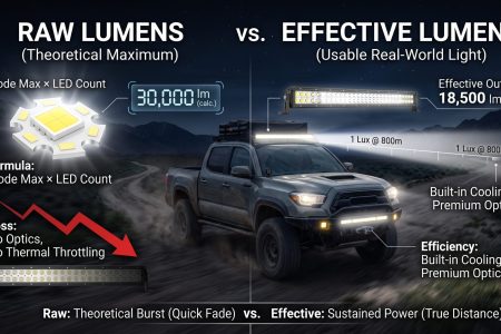
This distinction explains why a headline figure from a datasheet or a brief pulse measurement may not equal what a finished light bar produces after it warms. LED packages are commonly characterized under defined electrical and thermal conditions. A cold or short-pulse measurement may reduce self-heating compared with continuous operation. In a complete lamp, the board, housing and driver warm up over time; output can change as the assembly approaches a stable operating state. The lamp’s optics also affect how much light is directed into the measured area.
High drive current can increase both the immediate electrical input and the heat generated at the junction. If a design raises current to increase initial output without providing adequate thermal capacity, the steady-state junction temperature may exceed the intended range. The result could include output droop, color shift, reduced life, protective dimming or permanent degradation depending on the design and exposure. The relation is not necessarily linear over the complete operating range, so doubling current should not be assumed to double output or produce a predictable temperature increase.
The lens and reflector matter too. Their temperature can affect materials, seals and optical performance. Dust, moisture, surface damage or a change in reflective coatings can reduce useful beam output even if the LED junction temperature is acceptable. Conversely, a thermal issue can occur even when the emitted beam still appears bright to the eye. A photometric measurement under controlled conditions is more informative than judging apparent brightness after dark.
Color is another reason to interpret measurements carefully. Different color channels or phosphor systems may respond differently as temperature changes. A lamp containing multiple LED types may show a different chromaticity shift from a single-color source. The DOE’s old fact sheet includes comparisons across colored LED types that should not be generalized to all current products. For a specific product, request chromaticity or color-maintenance data from a defined operating range if color consistency is important.
Heat and the long-term life of a complete lamp
LED lifetime is often described using a lumen-maintenance threshold, such as the time until output falls to a stated fraction of its initial level. A projection for an LED package does not by itself tell a buyer how long an enclosed light bar will continue functioning. The completed fixture includes a driver, printed circuit boards, connectors, solder joints, seals, gaskets, optics, housing finishes and mechanical attachments. Any subsystem may become the limiting element.
The U.S. Department of Energy’s 2014 third-edition lifetime guide explains that luminaire life depends on the reliability of multiple subsystems. It notes that electrical control, thermal management, optical conditioning, mechanical support and protective materials all contribute. DOE specifically cautions buyers against relying on LED-package lumen maintenance as an unreliable proxy for complete luminaire lifetime. It recommends qualifying suppliers, understanding test methods, asking for data and reading warranty terms. This guidance was written for general illumination, so its life-reporting framework is useful context; it is not a test standard tailored to automotive light bars.
Heat accelerates some aging processes in semiconductor materials, phosphors, encapsulants, solder and nearby electronics. The exact acceleration depends on construction and material. A single elevated-temperature experiment cannot automatically be converted into a road-use lifetime without a validated acceleration model for the affected components and failure modes. DOE’s lifetime document explicitly says it is guidance rather than a universal model that predicts the reliability of every system. Treat a specific operating-hour claim as meaningful only when its method, failure definition and supporting component or luminaire data are clear.
The DOE’s 2007 fact sheet illustrates how sensitive projected life can be to junction temperature in one historical comparison: it describes a test with an 11°C difference in Tj and a large change in projected hours to a 70% lumen-maintenance point. That example is not a universal multiplier. It applies to the LEDs and study assumptions represented in that chart, which included extrapolation beyond measured test hours. Do not apply the reported percentage to a current light bar or infer a particular warranty life from it. Its proper lesson is that temperature can materially affect aging and that a small measured difference can matter in a given design.
Life claims should state what ends the clock. Does the test stop when light output falls below a threshold, when the driver fails, when the lamp no longer starts, when color leaves a tolerance, or when water ingress appears? Some products can retain light output while suffering a driver or seal failure. Others may continue to operate with output below the intended use level. A buyer should compare the manufacturer’s claim with the actual product warranty and ask which failure modes are covered, which are excluded, and whether replacement parts will be available.
The driver can be the limiting part
An LED driver controls the current delivered to the emitters and adapts vehicle electrical input to the LED assembly. Depending on the architecture, the driver may include switching components, inductors, capacitors, protection circuits and control electronics. These components have their own electrical losses and thermal limits. The driver can be mounted on the same board as the LEDs, on a separate board inside the housing or in an external module. Its position affects both cooling and exposure to vibration, moisture and electrical noise.
A light bar may have a high-quality LED package and still fail early if a driver component operates outside its intended temperature range. Electrolytic capacitors, semiconductors, solder joints and connectors each have different aging and failure modes. The correct component rating and actual hot-spot temperature matter more than a general statement that the driver is “waterproof” or “automotive grade.” A product-level thermal test should check the driver area as well as the LED board and housing.

Vehicle electrical conditions introduce additional variables. A nominal 12-volt system does not remain at one voltage in every operating state. Alternator charging voltage, start-stop cycles, load-dump transients, reverse polarity, jump starts and wiring losses can influence the driver. Those are electrical robustness issues as well as thermal ones: an inefficient or poorly matched driver may heat more at a given output, and an electrical fault can create localized heating. The lamp’s input specification, fuse, relay, wire gauge and installation manual should be followed.
When diagnosing a suspected thermal problem, separate the lamp from upstream supply issues. A hot connector, undersized wire or loose ground can heat at the connection while the bar’s LED board is cool. A driver fault can cause output instability or dimming that resembles a thermal protection cycle. A temperature-dependent failure may occur only after several minutes, but not all delayed failures are thermal. Record supply voltage and current at the lamp as well as case temperature, and stop if wiring insulation softens, a connector discolors, smoke or odor appears, or the installation becomes unsafe.
A useful manufacturer question is whether the driver’s maximum-rated temperature is a component rating or a measured value in the finished lamp. Ask where the driver is located, what temperature it reaches at the declared input and ambient conditions, whether the product has thermal protection, and what protection does when it activates. If a lamp uses automatic dimming, confirm whether the protection threshold and recovery behavior are documented. Do not assume that every LED bar uses an active temperature sensor; some depend on passive thermal design alone.
What a housing and fins can and cannot do
The housing provides structure, environmental protection, a path for heat spread and an external surface from which heat can leave. Aluminum is common because it is relatively light, readily formed or cast, and conducts heat better than many plastics. But the choice of material does not establish the temperature that the LEDs will reach. The thermal connection between the board and the housing, the housing’s size and geometry, the amount of heat generated, and the surrounding conditions all influence the result.
Fins increase surface area that can exchange heat with air. Their benefit depends on orientation, spacing, depth, thickness, material and airflow. Fins arranged for a horizontal bench test may perform differently when a bar is mounted vertically, behind a grille, under a roof rack or within a recessed bumper. If the gaps are too narrow for useful airflow, adding more fins can add weight and area without proportionally improving cooling. A vehicle traveling at speed may provide forced airflow, while a stationary work vehicle may have only natural convection. A fair test should state which case it represents.
The exterior enclosure also has to survive the environment. Thin fins can be vulnerable to impact or bending; wide slots may collect mud, leaves or ice; cavities can retain water or road salt; and brackets can obstruct the rear surface. A sealed housing can protect electronics but must still move heat out through its walls. Gaskets, adhesives and coatings may insulate some surfaces, and corrosion or a damaged finish can affect both durability and thermal contact. Product designers balance cooling area with impact resistance, sealing and manufacturability.
Buyers should regard visible fins as a design clue, not test evidence. Compare the housing with product-level measurements, and ask whether the reported temperatures were taken with the lamp installed in its intended orientation. A close-fitting bar in a bumper cavity is not equivalent to a lamp suspended in open air. If a manufacturer offers multiple mount styles or accessories, confirm whether the additional brackets, covers or guards change the required clearance around the heat-dissipating surfaces.
Do not drill, sand or modify a sealed housing to create more airflow unless the manufacturer explicitly approves the change. Altering a casting can expose electronics to water and vibration, weaken a mounting point or void the warranty. Nor should a user apply a new coating or thermal paste externally in an attempt to lower a surface temperature. Heat management depends on the designed interfaces inside the assembly; an improvised modification can make one condition better while introducing a more serious failure mode.
Ambient conditions change the result
Ambient temperature is the temperature of the surrounding air used as a reference for the thermal test. If the same product operates at a higher ambient temperature, there is generally less temperature difference available between the housing and the air to move the same amount of heat. This can raise component temperatures, depending on power, airflow and the system’s thermal resistance. A light bar that passes at room temperature may run hotter on a sunlit vehicle or in a warm engine compartment.
Air movement also matters. Vehicle speed can increase convection across exposed surfaces, but airflow is not guaranteed to reach every mounting location. A bar behind a grille, above a winch, close to a windshield or nested behind a fairing may receive turbulent or restricted air. At idle, the vehicle may provide little forward airflow while the alternator continues to supply the lighting load. Mud, dust, insect debris or snow can change the effective surface and obstruct passages. A thermal report should identify whether it uses still air, forced air or an installed vehicle arrangement.
Solar loading can add heat to dark surfaces before the lamp is switched on. Nearby engine, radiator or exhaust heat can raise the local environment beyond the weather-station air temperature. Enclosed work areas and slow-moving vehicles may have a different temperature profile from highway travel. If the light bar is intended for stationary use, a highway wind-tunnel result may not describe its worst operating condition. Conversely, a single high-temperature still-air test should not be presented as the only way the product will operate in normal use.
Vehicle electrical input and ambient temperature should be varied independently in a meaningful validation plan. A higher input voltage may change driver losses or operating current, while warmer air reduces the temperature gradient for cooling. The test should hold each condition long enough for the relevant areas to stabilize, record the voltage at the lamp, and define how “steady state” was determined. The driver and LED board may reach different stabilization times.
Weather resistance and cooling interact. A waterproof cap, protective lens, dust cover or accessory guard can affect heat dissipation. Cleaning instructions matter because pressure washers can damage seals, and packed dirt can block fin channels. Salt deposits may corrode exposed metal or fasteners. The owner should follow the product’s installation and maintenance guidance; no single ambient number can represent every climate, route and mounting position.
How to read thermal data from a manufacturer
Good thermal evidence starts by identifying the exact product and configuration. Ask for the part number, LED package or board revision, driver version, mounting orientation, supply voltage, input current and control mode. If the same product family offers different lengths, optics or wattage variants, do not assume data from one member applies to every variant. A change in emitter count or drive current changes both heat generation and the thermal field.
Next, check the measurement location and instrument. A report might give junction temperature calculated from a manufacturer-defined measurement point, an LED-board temperature near the solder pad, the driver case temperature or a surface reading on the rear housing. Each is useful for a different question. The report should identify sensor type, placement, attachment method, calibration and measurement uncertainty. A remote infrared reading of a reflective surface is not directly comparable with a thermocouple bonded to a matte board point.
The test conditions should include the ambient temperature, airflow, orientation, mounting fixture, warm-up duration, input voltage, measured current and whether the lamp was run continuously or cycled. If output is reported, the photometric method and timing matter: was the flux, illuminance or intensity measured at initial turn-on, after thermal stabilization, or after a longer run? A light bar’s beam pattern and optics affect the useful output, so raw chip lumens are not equivalent to system photometry.
Check whether the stated temperature is a measured maximum, a model result or an absolute rating from a component datasheet. A component’s absolute maximum rating is not a recommended continuous operating target or proof of long life. A calculated junction temperature depends on the assumed heat flow and the exact thermal-resistance definition. A maximum driver case rating does not show the actual temperature of the hottest internal switching element. Each number needs its context.
Finally, distinguish short-term thermal behavior from reliability evidence. A one-hour thermal soak can show that output and temperature reached a particular condition, but it does not establish years of vibration, moisture exposure or temperature cycling. A long life projection should define the failure criteria, sample count, aging method, acceleration assumptions, observed failures and any extrapolation. DOE’s 2014 lifetime recommendations emphasize system-level evidence and candid reporting; they do not provide an automotive-light-bar test protocol or guarantee a particular lifetime.
A practical thermal test for a light bar
A useful comparison test begins with a repeatable setup. Mount both products in the same orientation and with the same bracket clearance. Use the voltage specified by each product, and measure voltage at its input terminals under load. Put both lamps in the same ambient environment with the same airflow. Keep a safe distance from combustible materials, protect the circuit with an appropriate fuse, and secure the equipment so the test does not expose people to a moving vehicle or an unsafe beam.
Record the test before switching on: product identifiers, ambient temperature, mounting height and orientation, supply voltage, room or vehicle airflow, sensor locations and the time. Measure the LED board or specified case point only if the lamp’s construction allows safe access and the manufacturer’s data identify the correct location. If the housing is sealed, do not open it to attach a sensor unless the manufacturer provides an approved procedure. A surface thermocouple can be attached to the rear housing, but label that value as housing temperature rather than junction temperature.
Run the light in its normal continuous mode and record temperatures at regular intervals until readings approach a stable plateau or until a defined maximum duration is reached. Record input current and watch for output dimming, flicker, color changes, unusual odor, audible changes or connector heating. If any unsafe symptom appears, switch off safely and let the product cool before inspecting it. Do not touch a hot housing to estimate its temperature. Use an appropriate sensor and keep the measurement wiring away from the fan, belt, exhaust or other moving and hot vehicle parts.
After the thermal run, compare optical output only with suitable equipment and the same geometry. A handheld lux meter can show change at one point, but its reading is not total luminous flux and is sensitive to aim. A calibrated integrating sphere or goniophotometer provides different system-level information. For a basic field comparison, use a fixed target distance, stable mounting, repeatable aim and a controlled environment; state the limitations. A photograph of a beam pattern with automatic camera exposure is not a reliable brightness comparison.
Repeat a test if initial results are inconsistent, and preserve raw readings rather than reporting only a maximum. Multiple samples can help reveal production variation. The test should not defeat thermal protection, bypass a fuse or exceed the product’s voltage rating. Never test a vehicle electrical circuit by inserting an ammeter incorrectly in series with high-current wiring. If you do not have a suitable current clamp, temperature probes or electrical experience, ask a qualified technician or laboratory to measure the assembly.
Keep the aim and safety of the light in mind. A thermal test is not a road-legal or photometric approval test, and a cool-running bar may still produce glare or be unsuitable for public-road use. Local regulations and product instructions still apply. In the same way, a high measured temperature at the outside housing is not automatically proof that the LED junction exceeded its maximum. Report exactly what was measured, and do not turn a quick comparison into a universal product ranking.
Installation can help or hurt cooling
Installation determines the boundary conditions around the light. Before mounting, check the product’s specified orientation, clearance, bracket location and cable exit. The bar should not be wedged into a space that traps heat or places the housing in contact with an unintended insulator. A grille opening that looks generous from the front can still channel air away from the rear fins. For bumper or roof installations, follow the vehicle and lamp makers’ instructions and account for airbag sensors, body reinforcements, wiring, corrosion protection and structural loads.
Do not cover heat-dissipating surfaces with vinyl, a protective sleeve or an unapproved weather shield. If a rock guard or lens cover is designed for the lamp, check whether the manufacturer changes the allowable duty cycle or temperature limit when it is installed. A cover may help protect optics from damage but can also affect airflow or retain heat. Remove and clean only in the way specified, and recheck seals and fasteners after maintenance.
The fastening interface matters too. A bracket can conduct some heat, obstruct part of the housing or concentrate vibration at a mounting point. Use the supplied brackets and torque instructions, avoid overtightening into a thin casting, and make sure the lamp cannot move under vibration. An incorrectly aligned bar may direct light into the hood, windshield or mirrors; that creates a glare problem without improving useful illumination. Thermal and optical setup should be checked together.
Electrical installation can introduce separate hot spots. Use the recommended conductor size and fuse, appropriate relay or controller, sealed connectors and strain relief. Route wires away from exhaust components and sharp edges. A loose connector has contact resistance that can create localized heating; it may appear discolored or brittle even when the lamp housing is within normal limits. If cable or connector temperature rises unusually, turn the circuit off, let it cool and have the connection assessed before further use.
After the first operating period, inspect bracket security, cable routing, connector condition, fin cleanliness and the gap around the housing. Recheck after the first off-road trip because impact and vibration can loosen hardware or move a lamp into an airflow obstruction. A vehicle that has been modified with a grille, bumper, rack or winch may need its cooling clearance checked again. Do not assume a previous installation remains suitable after bodywork or accessory changes.
Symptoms that can point to heat
Heat-related behavior can include output falling after several minutes, color changing as the lamp warms, protective dimming followed by recovery after cooling, repeated shutdown during stationary operation, or a driver that works again after a cool-down period. These symptoms are clues, not a diagnosis. A loose connector, low system voltage, poor ground, incompatible PWM controller, failed relay or internal driver fault can produce similar flicker or dimming. Keep the electrical system in the differential diagnosis rather than replacing the lamp based only on timing.
Record when the issue starts and what conditions are present. Does it happen immediately after startup, only at idle, after the lamp has been on for a while, in hot weather, behind a cover, or after the vehicle moves slowly through mud? Does output recover by itself, after switching off, or only after a long cool-down? Does a second lamp behave the same way? Those details help a technician separate thermal protection, vehicle supply changes and component failure.
Begin with safe, non-invasive checks: inspect mounting clearance, blocked fins, mud or debris, cable damage, connector seating and obvious corrosion. Verify that the lamp is operated in the mode and input range specified by its manual. Do not remove sealed covers, probe live high-current terminals, bridge a protection circuit or keep cycling a lamp that smells burnt. If a plug is melted, insulation is soft, the housing is cracked or water has entered the enclosure, stop using it until the cause is corrected.
A handheld infrared thermometer may help compare the same matte location before and after an issue occurs, but its reading is not the LED junction temperature. Shiny aluminum can reflect nearby heat and give misleading results. A thermal camera can locate unusually hot connectors or driver areas, but it cannot prove which internal component has failed without electrical and design information. Do not compare readings taken at different points or ambient conditions as though they were one controlled test.
If the problem repeats, preserve evidence for warranty service: the part number, installation location, input voltage under load, ambient condition, operating duration, symptom, photos of wiring and any measurements with sensor location identified. Do not open the lamp or alter the wiring if that would invalidate warranty terms or create a safety hazard. A qualified automotive electrician can check voltage drop, alternator output and connector condition. The product maker can interpret the lamp’s thermal protection and component limits.
Buyer checklist: questions worth asking
Ask the manufacturer what the wattage figure represents: nominal LED-package rating, maximum input, measured electrical input at a stated voltage, or an output claim. Ask which LED package and driver revision the product uses, but remember that brand-name emitters do not establish finished-lamp performance. If package data are available, request the operating current and thermal resistance definition that apply to that exact part number.
Ask where temperature was measured and whether the value describes the junction, a specified solder point, board, driver or external housing. Ask how the junction temperature was derived, if it is reported. Request the ambient temperature, airflow, mounting orientation, input voltage, run duration, sample count and stabilization criterion. If output is reported, ask whether it was measured before or after the lamp reached thermal equilibrium and whether the value is a package claim or a complete-luminaire test.
Ask what happens if the lamp exceeds its intended operating temperature. Does it automatically reduce current, shut down, issue a fault indication or rely on passive design? Does it recover automatically after cooling, and at what conditions? Ask whether adding a protective cover, changing the mount or placing the bar behind a grille changes the duty cycle. Do not bypass any thermal control or fuse to obtain more light.

Ask for warranty terms that cover the complete assembly, including the driver, seals, connectors and optics. Confirm the duration, exclusions, required installation method and service process. A warranty is not a substitute for reliability data, but it gives the buyer a practical remedy if a product fails. Check whether the manufacturer can provide replacement parts or support for a vehicle-specific mounting setup.
Finally, compare products under the same use case. A bar intended for intermittent work-light operation may not be specified for continuous use at full output in a stationary hot environment. A compact unit may fit better but have less exposed area. A high-power model may need specific clearance. Ask the seller to distinguish tested information from assumptions and avoid purchasing on advertised watts, a fin photo or a chip-brand name alone. SAEC’s LED light bar color temperature guide explains another specification that is often mistaken for performance, while the light bar flickering guide covers electrical symptoms that can resemble thermal problems.
For product exploration, compare an LED light bar and compact LED pods only after confirming their exact fit, beam, current draw, mounting clearances and approved operating limits for the vehicle. A product page can describe available options, but it is not a substitute for the installation manual, complete-lamp test data or local road-use rules.
Frequently asked questions
Does an LED light bar get hot?
Yes. LEDs emit little infrared compared with incandescent lamps, but electrical input still creates heat at the LED junction, driver and other components. A warm housing can be normal because it is receiving heat from the internal assembly. The external temperature alone does not show the LED junction temperature.
Does a larger heat sink always mean better cooling?
No. Surface area helps only when heat can reach that surface and the design can transfer it to surrounding air. Material, board-to-housing contact, fin spacing, orientation, airflow, mounting clearance and ambient temperature all affect performance. Product-level thermal measurements are more useful than appearance alone.
Can I use a thermometer to measure LED junction temperature?
An ordinary infrared thermometer measures surface radiation, not the microscopic LED junction. Junction temperature is normally estimated using a package-specific method, such as a defined measurement point and the exact component’s thermal resistance. Follow the manufacturer’s test instructions and do not substitute a housing reading into a package equation.
Why does a light bar dim after it has been on for a while?
Possible causes include thermal protection, output change as the assembly warms, voltage drop, a loose connection, driver failure, an incompatible controller or a vehicle charging issue. Note how long it takes, the mounting location, ambient condition and electrical voltage under load. Stop using the lamp if wiring or connectors show heat damage.
Is a hot housing a sign that the light bar is defective?
Not necessarily. A housing that receives and releases heat may become warm during operation. Compare the measured temperature with the product’s stated limits and test conditions. A hot spot, an unusual rise at the connector, protective shutdown or output loss needs investigation, but a touch test cannot establish whether the junction is within specification.
Can I add fins or thermal paste to lower the temperature?
Do not modify a sealed light bar unless the manufacturer approves the change. External fins may not connect effectively to the internal board, and drilling or opening the housing can compromise sealing, mechanical strength and warranty. Use the specified mounting clearance and installation hardware.
Does a lifetime rating for the LED chip guarantee the light bar’s life?
No. The driver, solder joints, seals, optics, connectors and housing can fail or limit useful service life. Ask for system-level evidence and read the warranty. A package’s projected lumen maintenance is not a complete-luminaire lifetime test.
Can a low-cost thermal camera prove a product is safe?
No. A thermal camera can help locate relative hot areas on accessible surfaces, but emissivity, reflections, resolution and camera calibration affect readings. It cannot see the LED junction through an opaque enclosure or independently verify electrical safety. Use it as one diagnostic tool, not as product certification.
Conclusion
An LED light bar is an optical product built around a thermal and electrical system. The LED junction, board, thermal interfaces, housing, driver and surrounding air all affect how heat moves and how the lamp performs after it warms. A visible heat sink is only one part of that chain. Temperature readings become useful when their locations and test conditions are explicit.
When comparing lights, ask whether data describe the LED package or the complete lamp, how the junction estimate was made, what output was measured after stabilization, and whether the driver and other subsystems were included in reliability claims. Install the product with its specified clearance, airflow and wiring. If a lamp dims, flickers or develops an unusually hot connection, investigate safely and involve a qualified technician when electrical testing is needed.
Editorial note
Prepared by the SAEC Lighting Engineering Team, Foshan. Last updated October 13, 2026. Thermal concepts and equations are simplified for explanation; component calculations must use the exact manufacturer’s datasheet and approved measurement method. This article is not product certification, an installation instruction or an automotive electrical repair procedure.
Sources
- U.S. Department of Energy: Thermal Management of White LEDs — heat path, junction temperature, current, ambient temperature and historical thermal-performance examples.
- U.S. Department of Energy: LED Luminaire Lifetime, Third Edition — system-level reliability and lifetime reporting; not an automotive light-bar test standard.
- Nichia: Automotive LED Application Notes — current junction-temperature calculation note for selected component series.
- Nichia: Thermal Resistance Values for Selected LED Series — package-specific values; do not apply to other component families.
 by

