


On this page
LED light bar flickering usually comes from an unstable supply or connection, an incompatible control signal, charging-system ripple, a relay or driver fault, or heat protection. The timing of the symptom helps narrow the cause, but one visual pattern does not prove which part has failed. Start with safe observation and the exact product and vehicle instructions before testing or replacing components.
Prepared by the SAEC Troubleshooting desk. This guide covers general diagnostic logic for auxiliary LED light bars; it is not a vehicle-specific wiring diagram. Follow the vehicle and lamp manuals, and refer energized-circuit measurements or repeated fuse failures to a qualified automotive electrician. Last updated October 12, 2026.

Why is my LED light bar flickering?
A light bar needs stable power, a reliable return path, and a control signal its driver can accept. If any of those conditions changes quickly, the LEDs may visibly pulse, dim, blink out or make a rapid strobe-like pattern. A poor connector can open and reconnect as the vehicle moves. A weak ground or high-resistance positive connection can lose voltage under load. A relay or controller may chatter when its coil receives a pulsed or marginal signal. A lamp’s internal driver may also be failing or entering thermal protection.
The engine-running condition is a useful clue but not a diagnosis. If the bar is steady with the engine off and flickers after startup, the charging system, a factory-controlled trigger, a changed supply voltage, a bad engine/body ground or interaction with another accessory may be involved. If it flickers both with the engine off and running, inspect the lamp, fuse holder, connectors, relay harness and battery feed. If the symptom appears only over bumps, suspect a moving connection or damaged wire before replacing the lamp.
The word “flicker” can describe different symptoms. A slow flash every few seconds may indicate a controller cycling or thermal shutoff. A fast pulse can occur when a relay or lamp driver sees a pulsed input. A brief dip during engine cranking may be related to normal system voltage change or an electrical fault. A bar that dims only when a winch or compressor starts may share an overloaded supply or ground. A buzz from a relay can be mechanical chatter, while a faint high-pitched sound from a driver may be a component vibration that does not match visible output changes.
Use the symptom’s timing to create a testable description: one bar or both; engine off or running; cold or hot; stationary or over bumps; all modes or one setting; with another load switched on or off; and whether the dashboard shows a warning. Note whether the radio, GPS, camera or other electronics also change. Those details help separate a local lamp fault from a vehicle power or electromagnetic issue.
Do not begin by adding a “CAN bus decoder,” resistor, capacitor or bigger fuse. These parts are not universal fixes. Some modern vehicles use pulse-width modulation (PWM) or load monitoring on specific lighting circuits, but that does not mean an auxiliary bar should be connected directly to that circuit or that every flickering bar needs a decoder. The correct interface depends on the vehicle’s output, accessory driver and manufacturer instructions.
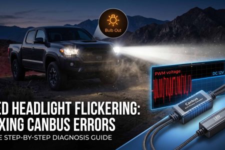
This guide distinguishes a visual flicker from radio interference, explains safe observations and inspections, and describes when a trained technician should test voltage drop or charging-system ripple. For an auxiliary light bar that does not turn on at all, see SAEC’s separate LED light bar no-light diagnostic guide. For headlamp-bulb flicker and CAN bus warnings, see SAEC’s distinct LED headlight flicker article. Those are different symptoms; a bar that remains illuminated but unstable needs its own set of questions.
What does the flicker pattern tell me?
The pattern helps prioritize inspection, but it does not identify the defective part by itself. Begin with a short written symptom log. Include when the problem happens, what else is operating and whether the output changes in one lamp or both. Do not reproduce the issue while driving if doing so would distract you or expose other road users to glare. Park safely, switch off the lamp when it is not needed and use a helper if another person must observe the light.
| Observation | Possible area to investigate | What the observation does not prove |
|---|---|---|
| One lamp flickers while a paired lamp stays steady | Local connector, branch wire, ground, LED driver or lamp electronics | That the lamp itself is definitely defective |
| Both lamps flicker at the same time | Shared feed, fuse holder, relay, trigger, ground, charging voltage or controller | That the alternator is the cause |
| Flicker starts only after engine startup | Charging-system condition, factory trigger signal, shared ground or electrical interaction | That the light is incompatible with the vehicle |
| Flicker occurs over bumps or vibration | Loose connector, terminal retention, harness strain, internal damage or ground movement | That a stronger fuse or thicker wire is the right repair |
| Output fades after several minutes and returns when cool | Thermal protection, restricted airflow, driver fault or a connection heating under load | That the LEDs alone are overheating |
| Relay buzzes in rhythm with the lamp | Coil supply or control signal cycling, incompatible trigger or relay issue | That every relay buzz requires a CAN bus decoder |
| Radio or GPS is affected when the bar turns on | Conducted or radiated noise, antenna route, ground, receiver or another accessory | That visible flicker and radio interference share one fault |
| Flicker occurs only in one dimming mode | Controller, PWM setting, dimmer compatibility or that specific driver mode | That the battery voltage is unstable |
When LED light bar flickering affects one lamp but not its paired unit, compare the individual branch rather than swapping components immediately. If the lamp and its connector are interchangeable under the product instructions, a qualified installer may be able to determine whether the symptom follows the lamp or stays with the harness branch. Do not perform a swap if the harness is damaged, the circuit is hot, the connector is wet, or the product instructions prohibit it. Record the lamp and harness serial or part identifiers before changing anything.
A both-lamp symptom points attention toward something shared by the two branches: a common fuse holder, relay, supply cable, ground point, controller or trigger. But two lamps can also share the same environmental cause, such as temperature or a selected operating mode. If one lamp’s internal driver fails and causes a shared controller to reset, both may respond. The wiring diagram and product instructions determine which parts are actually shared.
A timing clue has to be separated from coincidence. If the light flickers only when the engine is running, compare the exact condition: does it start at idle, after raising engine speed, when the alternator loads change, or only when a factory headlamp is switched on? Do not repeatedly rev the engine or activate bright lamps in public traffic to reproduce a complaint. A trained technician can use an approved test procedure to compare the system at safe operating points.
If a sound accompanies the flicker, locate its source without placing hands near moving or hot parts. A helper can observe from a safe position while the engine is off, or a technician can isolate the accessory under the vehicle manual procedure. A relay that physically chatters sounds different from a faint electronic coil whine inside a driver, although a sound alone cannot identify the circuit. Do not remove relay covers, short terminals or bypass protection to listen for a change.
What should I do before checking the wiring?
Park on firm, level ground away from traffic. Set the parking brake, select the vehicle’s safe parked state and switch off the auxiliary lights. Follow the light manufacturer’s instructions for isolating power and the vehicle owner’s manual for battery or electrical-system service. On vehicles with battery monitoring, start-stop, hybrid systems, stored-energy components or security settings, disconnecting a battery can require a specific procedure. Do not assume that removing a battery terminal is a universal first step.
Let hot lamps, wires and nearby engine components cool before touching them. A light bar can remain hot after use; a connector or wire with high resistance can also heat under load. If insulation is soft, discolored or melted, if a fuse holder smells burned, if there is smoke, or if a wire is too hot to safely approach, stop using the system and do not energize it again. Repeated heat is a warning sign, not a reason to install a larger fuse.
Do not bridge a fuse, substitute a higher-rated fuse, connect wires by color guess, or bypass the relay. The fuse is part of the circuit protection. If it opens repeatedly, the cause could be a short, overload, damaged wire, failed component or incorrect installation. Repeatedly replacing the fuse can increase fire risk. Use only the fuse value and type specified by the product and vehicle manufacturer for that exact circuit.
Do not use a test light or multimeter on an unknown vehicle-control circuit. Modern vehicles may use pulse-width modulation, electronic high-side or low-side drivers, current monitoring, networked modules and sensitive sensors. A probe can load or damage a circuit, create a fault code or cause a system to behave unexpectedly. Never probe airbag, pretensioner, high-voltage, battery-management, CAN bus or other safety-critical wiring as part of a generic light-bar check.
A digital multimeter can be useful in trained hands, but meter mode and probe location matter. An ammeter setting connected across a battery or supply can create a short circuit. A low-current test light can damage a control circuit. A static voltage reading with the lamp off may not reveal voltage drop under load. Follow a named service procedure, use a suitably rated instrument and know how the circuit is isolated and energized. If any of those conditions are unclear, stop and have a qualified automotive electrician test it.
Protect your eyes from high-output lamps. Do not look directly into the bar while switching modes. Avoid testing where the beam can reach traffic, neighbors, pedestrians or reflective surfaces. If the bar may be wired to an automatic high-beam or vehicle signal, prevent an unexpected activation before inspection by following the product instructions. Keep loose clothing, jewelry, hair and test leads away from belts, fans and pulleys when a technician must run the engine.
A vehicle warranty, fleet policy or local law may restrict modifications. Before changing a factory harness, relay, fuse, headlamp trigger or body ground, consult the vehicle manual, accessory instructions and an approved installer. If the symptom began after a recent repair, lift, battery change, bumper replacement, radio installation or lighting upgrade, record that history. Reversing a change without documentation can obscure the cause and create a second problem.
What are seven safe checks for a flickering light bar?
The following sequence begins with observation and visual inspection. It is not an instruction to probe unknown vehicle wiring or dismantle the lamp. Use the exact wiring diagram and service procedure supplied for the vehicle and light. If the symptom includes smoke, heat, repeated fuse opening, a vehicle warning or a safety-system issue, skip the remaining checks and seek professional diagnosis.
1. Record the conditions. Note whether one or both lamps flicker; whether it happens with the engine off or running; whether the bar is cold or warm; which modes are selected; and whether the symptom changes with road movement, another electrical load or factory lighting. Include the vehicle year, make and model, lamp model, harness model and any recent work. A good description helps avoid random part replacement.
2. Confirm the product controls. Check whether the bar has a controller, dimmer, Bluetooth module, switch panel or multiple output modes. Read the instructions for the selected mode and supply. Confirm that the button, switch and indicator show the mode you intended. A controller that is not fully connected or a setting that cycles automatically may look like an electrical fault. Do not reset or reprogram a controller unless the product manual describes that action.
3. Inspect visible wiring with power isolated. Look for a loose connector, pin not fully seated, water, corrosion, crushed insulation, abrasion, sharp-edge contact, strain at the lamp, cable too close to exhaust parts or an unsecured harness that can move. Check that any connector seal is present and the latch engages. Do not pull on wires by force. If a connector is discolored, melted or wet inside, stop and follow the manufacturer’s repair or replacement guidance.
4. Review the fuse and relay match. Compare the installed fuse type and value with the exact kit instructions. Confirm that a relay harness is the one intended for the lamp and vehicle. Do not assume a visually similar relay is equivalent. If the fuse has opened or the relay is hot, do not repeatedly power the circuit. A qualified technician should identify the cause and verify the load, wiring and protection before the system returns to service.
5. Check mounting and vibration. With the system de-energized, inspect whether the lamp is securely mounted and whether the harness is rubbing, pulling or flexing at a connector. Confirm that the bracket, fasteners and body panel are not loose. A light that vibrates excessively can stress internal connections, but changing the bracket or tightening a fastener should follow the product’s torque and mounting instructions. Do not reach behind a live lamp or place hands near a moving fan.
6. Compare accessory and vehicle behavior. Only if the instructions permit a safe comparison, note whether the symptom is tied to the engine, a factory lamp, another accessory or a specific dimming input. Do not disconnect or splice a factory circuit simply to see what happens. A vehicle-specific diagnostic tool or interface may be needed to observe the intended signal. If a warning appears on the dashboard, record it and consult an authorized repair facility.
7. Decide whether to stop or refer it. If the visible checks identify obvious damage, a hot connector, a missing seal, a loose ground or an incorrect part, use the manufacturer’s documented repair path. If the symptom persists, if the trigger circuit is unknown, if a fuse opens again, or if the vehicle’s electronics behave unexpectedly, stop using the bar and refer it to a qualified installer. Ask for a loaded-circuit voltage-drop check, charging-system evaluation or product test only where appropriate.
The sequence is designed to rule out simple external causes before replacing a lamp. It does not guarantee that the component itself is good. A lamp can have an internal driver problem that is not visible from outside. Conversely, a functioning lamp can flicker because its supply or trigger is unstable. If a replacement is needed, confirm the exact voltage range, current draw, connector, mounting and control requirements from the product documentation.
A symptom checklist can be more useful than a list of generic parts. Record whether the light flickers with the engine off, whether both sides change together, whether a relay clicks, whether the issue appears only after warm-up, whether another receiver is affected, and whether the installation was recently changed. Provide those notes to the technician and accessory supplier along with photos of the route and part labels. Do not publish private vehicle identifiers in a public support forum.

How can voltage drop or a poor ground cause flicker?
If LED light bar flickering appears only under load, inspect whether the bar receives adequate voltage while current is flowing. Resistance in a loose, corroded, undersized, damaged or overheated connection can consume part of the supply voltage. The lamp driver may then reduce output, shut down and restart, or enter a protection state. A ground-side restriction can cause the same type of problem as resistance on the positive side. Looking only at the positive wire can miss a poor return path.
The useful distinction is between voltage at rest and voltage under load. An open-circuit reading taken with the light off may show battery voltage even if a connector cannot carry current reliably. A continuity check may also pass through a weak connection that fails when the lamp draws current. Fluke’s automotive voltage-drop guidance explains that a voltage-drop test needs current flowing through the circuit to reveal restrictions. Exact limits should come from the vehicle or product manual; there is no one universal acceptable reading for every auxiliary-light circuit.
A trained technician may compare voltage at the source and at the lamp while the system is operating, then test the positive and ground sides separately using approved points. If voltage is lost on the positive side, the technician traces the feed through its fuse holder, relay contacts, connectors and cable. If loss is on the return side, the ground wire, terminal, chassis connection and bonding path need review. The test is only meaningful when the circuit is loaded and the meter is connected correctly.
A ground connection should be mechanically secure and electrically appropriate. Paint, rust, sealant, loose fasteners or incompatible materials may increase resistance. But the correct ground location is vehicle-specific. A nearby bolt may be part of a painted panel, an aluminum body, a sensor mounting point or a safety-related structure. Follow the vehicle and lamp maker’s grounding instructions; do not scrape paint or drill a new hole without authorization.
Longer cables have more resistance than short ones of the same conductor size, and higher current can make a weak connection more noticeable. The installation should use the conductor size, fuse, relay and connector specified for the load and cable length. A product’s wattage alone is not enough to select a fuse or wire gauge; voltage range, startup current, duty cycle, temperature, bundling, routing and kit design also matter. Use the manufacturer’s supplied harness unless the instructions specify an approved alternative.
A weak connection can create heat. If a connector becomes hot, the circuit may have excessive resistance or current; the plastic can soften and the fault can worsen. Do not touch a suspected hot connection while energized. After power is isolated and the parts cool, visually inspect for discoloration or deformation, then seek a qualified repair. Increasing the fuse rating to stop nuisance opening can expose wiring to damaging current and is not a safe repair.
A flicker over bumps often points toward intermittent contact rather than a steady voltage-drop problem. A terminal can be loose inside its housing, a crimp can be weak, or a cable can flex at the point where it enters a lamp or relay. A technician can reproduce a movement-sensitive fault using a controlled harness inspection while monitoring the circuit. Do not yank on the wires or apply force to a powered connector; that can create a short or make the damage worse.
The voltage-drop diagram below is conceptual. It is not a pinout or a recommendation to probe every point. The exact test points must come from the wiring diagram and product instructions. When the circuit includes a body-control module, PWM output, high-side switch or networked controller, the test method may differ from a simple battery-relay-lamp setup.
For a broader no-light diagnostic sequence, SAEC’s light-bar power-path guide distinguishes the load path from the control path. That article is not a substitute for the specific wiring diagram on the kit you own.
Can PWM or a factory trigger wire make an LED bar flicker?
Pulse-width modulation rapidly switches a signal on and off to control average power or communicate a control state. A lamp that expects steady DC may react visibly if it is connected directly to a pulsed output, depending on the pulse rate, duty cycle, driver design and the eye’s perception. Some vehicle lighting outputs are controlled or monitored electronically, so a wire that appears to be a convenient trigger may not provide a continuous 12-volt signal suitable for every relay or controller.
The distinction between a trigger and a power feed is important. A properly designed accessory harness may use a factory high-beam or auxiliary switch signal only as a low-current control input while drawing lamp power through its own fused supply. A vehicle-specific interface may be needed to interpret a PWM or monitored signal. The wiring diagram must state the intended connection. Do not power a high-current bar directly from a headlamp wire unless both the vehicle manufacturer and light manufacturer explicitly permit that configuration.
HELLA documents that pulse-width-modulated vehicle bulb outputs can cause some LED retrofit bulbs to flicker. That example concerns replacement bulb products designed to occupy a factory lamp socket. It should not be extended to claim that every auxiliary LED bar flickers because of PWM or needs a CAN bus adapter. Auxiliary bars can have a separate relay harness and control input. The bar’s own driver may also use PWM internally without any fault.
A control input can be wrong even if the lamp power feed is correctly fused. A relay coil may chatter if the input repeatedly crosses its pickup or hold threshold. A controller may restart if its input signal falls outside the documented range. A vehicle’s lamp monitoring may pulse a circuit briefly to check load while the driver believes the lamp is off. These possibilities require a vehicle wiring diagram or diagnostic information, not a generic “tap the high beam” instruction.
If the flicker begins immediately after installing a trigger wire, stop using that connection until its compatibility is confirmed. Compare the interface model and installation instructions. Confirm that the trigger lead is connected to the exact signal specified. If a warning appears, the original headlamp behaves oddly, or the bar affects other vehicle functions, remove the accessory from use and have a qualified installer inspect it. Do not add a resistor or decoder to mask a warning without understanding the effect on current and heat.
A resistor can draw additional current to mimic an incandescent lamp load. That extra current is converted to heat and may require a correctly rated mounting location. It can defeat a vehicle’s original load monitoring, increase harness load or create a thermal hazard if installed incorrectly. A CAN bus decoder is not a generic noise filter; the name does not guarantee that a product decodes every vehicle protocol. Use only an interface documented for the exact vehicle and accessory system.
If the product has multiple modes, a dimmer or a wireless controller, test only according to its instructions. A particular dimmed mode can use a different internal switching pattern from full output. If the bar is stable at full output but flickers when dimmed, the controller or low-duty mode may be relevant. That observation narrows the area to investigate but does not prove that the vehicle’s main supply is healthy.
PWM is one possible factor in auxiliary-light flicker; it is not a diagnosis by itself. A useful report to a technician includes the exact vehicle output used as the trigger, interface part number, relay/controller model, mode, timing of the flicker and whether the factory lamp or dash warning changed. With that information, the technician can compare the signal with the product’s specified input using the correct equipment and method.
Could alternator ripple make the light flicker?
An alternator converts mechanical energy into electrical output, and its rectifier and regulator help provide power for the vehicle. A charging system can include a small AC ripple component on its DC output. If a charging-system fault produces excessive ripple or unstable voltage, vehicle lights and electronics may show symptoms. Fluke describes abnormal alternator ripple as a possible sign of a failed rectifier diode or damaged stator winding and notes that flickering lights can occur among the associated complaints.
An alternator issue is more plausible when several vehicle systems change together, not only one accessory. Interior lamps, dashboard displays, headlights, battery warnings or other electrical equipment may also fluctuate. Even then, symptoms alone do not prove alternator failure. Battery condition, charging strategy, grounds, belt drive, high-current connections and accessory loads can produce overlapping clues. Modern smart-charging systems may vary voltage by design, so a single voltage reading without the vehicle’s procedure can be misleading.
A qualified technician can test charging voltage and ripple using a suitable meter or oscilloscope and the vehicle manufacturer’s steps. Fluke’s published method includes safety notes about keeping hands and leads clear of belts and pulleys, and it recommends probing at battery posts when access to the alternator output stud is unsafe. It also gives values for its own test approach; those values should not be treated as universal pass/fail thresholds for every vehicle, alternator, meter and operating condition.
Do not place meter probes near a moving belt, fan or exposed alternator terminal unless trained and equipped. A short circuit at a high-current battery or alternator connection can cause severe damage or injury. Do not disconnect the battery while the engine is running as an improvised alternator test. That can create voltage spikes and damage vehicle electronics. If a charging-system warning appears or multiple systems flicker, stop the accessory test and have the vehicle diagnosed.
The light bar may also be amplifying an existing supply issue. A high-current accessory can expose a weak battery connection or ground that was not obvious under lower load. This does not mean the lamp should be wired to a different random source. The system must be checked against the vehicle’s accessory capacity, supplied harness design, fuse protection and product current requirements. A vehicle’s alternator rating does not automatically guarantee that every optional load is supported in every idle, temperature or operating condition.
If the light flickers only when a winch, air compressor, heated equipment or another high-load device operates, consider the shared electrical load and wiring architecture. Use one change at a time and follow the equipment manuals. A heavily loaded electrical system may change voltage or expose a poor connection. If multiple loads share a circuit not intended for them, the proper correction may be a different approved power distribution plan, not merely a heavier fuse or thicker wire.
When only the LED bar is unstable and the rest of the vehicle is steady, the lamp’s driver, dedicated harness, relay, ground or trigger may be more likely than a system-wide charging fault. That is a prioritization, not certainty. A technician can compare the lamp’s input voltage, ripple and control signal under the exact fault condition. If the vehicle uses electronic power management, the measurement should be interpreted using its service information.
Why is the relay or light bar buzzing?
A relay contains a coil and moving contacts. A buzz or chatter can occur when the coil repeatedly energizes and releases, which can happen if its input or supply is unstable or incompatible with the relay. A loose relay in its socket, a damaged coil, a poor ground, a pulsed trigger or a controller cycling can also produce a sound. The sound’s rhythm can help: a sharp repeated click may track output pulses, while a faint high-frequency whine may come from a switching driver or inductor.
Do not assume that every sound is a defect. Some electronic drivers can produce a faint tone under certain loads or modes without visible output loss. The question is whether the sound is new, unusually loud, associated with flicker, heat, odor or a warning, or changes with vibration. If the relay housing or fuse holder is hot, the bar flickers, the contacts appear damaged, or the smell is burnt, stop using the circuit and seek service.
Never open a sealed relay or relay module to repair it in the field. Do not bridge its terminals or bypass its contacts. The harness diagram should identify the relay type and connections. Replacing it with a random automotive relay may change the coil current, suppression diode polarity, contact rating or control compatibility. The replacement must match the part number and instructions, particularly if the vehicle output is electronically controlled.
If the relay buzzes after a new installation, check the trigger source and interface first, with the power isolated and under the installation guide. A factory signal may be monitored or pulse-width modulated. If the relay is being fed from an output not designed for it, the fix may require a vehicle-specific interface or a different approved circuit. Do not solve chatter by selecting a larger fuse or increasing relay capacity without diagnosing the control path.
A relay that chatters after the vehicle warms up may be responding to voltage change, a hot connection, an overheating controller or an intermittent fault. If the sound appears only with one dimming mode, the mode’s control input could be involved. If it appears only over bumps, inspect mounting and terminal retention with power isolated. A technician can monitor the coil input and load output while safely reproducing the condition.
An unusual noise from inside the lamp may indicate the driver’s magnetic components vibrating, a fan or a thermal-control mechanism, depending on product design. Check the manual for normal sounds and operating modes. If the sound comes with light output instability, repeated resets, a burning odor, visible water or abnormal heat, discontinue use. A sealed lamp often cannot be serviced without compromising its environmental seal and warranty.
Why does the light flicker over bumps or after heating up?
A bump-sensitive symptom often points to an intermittent connection or harness movement. Vibration can move a terminal that is not fully seated, flex a weak crimp, pull on a lamp pigtail, or make a damaged section of wire touch a sharp edge. It can also reveal a loose mounting bracket or internal component. Inspect the accessory installation with power isolated and the vehicle parked. Do not create a dangerous road condition to reproduce the symptom.
Follow the cable from the light to the connector and relay, looking for strain at bends, unsupported weight, tight ties, abrasion and contact with exhaust or moving components. A harness can look intact from above while chafing on a frame edge underneath. Do not reach under an unsupported vehicle. Use approved lifting points and stands, or have a qualified shop inspect the underbody route. A zip tie can keep a cable from moving but should not crush its insulation or substitute for a designed strain relief.
Heat-related flicker can come from the lamp’s thermal protection, a failing driver, restricted airflow or a high-resistance connector heating under current. Some products deliberately reduce output at high temperature to protect components. The manufacturer’s manual should explain normal operating behavior. If the output returns after cooling, that pattern is useful evidence but does not distinguish intended protection from a defect.
Water or condensation can create another intermittent pattern. Check for visible external damage, missing seals, cracked lens or a connector that has been exposed. Do not open the lamp to dry it unless the manufacturer says that field service is allowed. A housing that is opened incorrectly can lose its sealing, and internal moisture may require a warranty or professional service decision. An IP code should be interpreted according to the product’s documented test and does not prove that a damaged installation remains sealed.
The history of the installation matters. A flicker that began immediately after a bumper replacement, suspension lift, grille change, winch installation, battery change or radio upgrade may be related to a moved cable, altered ground, sensor interference or a changed trigger. Compare the current setup with the installation diagram and any before/after photographs. Do not assume the most recently installed component is definitely responsible, but include the date and work performed in the diagnosis.
If the symptom is movement-sensitive, a qualified technician can perform a controlled harness wiggle test while watching voltage or signal at approved points. They can inspect crimp integrity, connector retention and ground performance under load. This test should not be done by shaking wires near hot, moving or energized components. If a connection visibly sparks, heats or loses insulation, stop using the accessory and repair the cause before further testing.
Is radio interference the same problem as visible flicker?
No. A radio may become noisy when an LED light bar turns on even if the light beam looks steady. That suggests an electromagnetic disturbance path, but a receiver or antenna fault can create a similar symptom. Conversely, a light can flicker because of voltage drop or an unstable control signal without causing noticeable radio interference. The two problems can share a source, such as a driver or poor ground, but one is not proof of the other.
A useful observation is which receiver is affected and when. Does FM reception change, AM static increase, GPS accuracy degrade, Bluetooth audio drop, or two-way radio receive a rhythmic pulse? Does the symptom follow one light, a pair of lights, a specific output mode or a particular cable route? A test with a different station or receiver can help distinguish a local signal-strength issue from accessory-related noise, but it is not an EMC compliance test.
CISPR 25 defines radio-disturbance measurements and limits intended to protect onboard receivers under its test conditions. A roadside radio comparison cannot reproduce its antenna, frequency, cable, detector, grounding plane or limits. It can still be a practical clue for a technician. Record the radio service, frequency or channel, accessory mode, engine state and whether reception returns immediately when the bar is switched off.
Do not add a random ferrite, filter or capacitor without guidance. A ferrite core may help only when used on the right conductor, frequency and location; a filter can alter the supply or create heat; a capacitor can draw inrush current or affect a monitored circuit. Ask the light manufacturer whether the unit has an EMC report and whether a specific filter or cable route has been validated. If the noise occurs across products or vehicle systems, an EMC technician may need to determine whether it is conducted or radiated.
A radio complaint that starts after adding a light may come from the light, controller, cable, installation or another accessory activated at the same time. To isolate the source safely, change one factor at a time while parked. If the issue persists with the lamp off, the receiver or antenna may be involved. If it follows the lamp across a suitable test setup, the product becomes a stronger suspect. Do not alter an antenna, vehicle data wire or safety-critical circuit as an experiment.
If radio interference accompanies light flicker, record both separately. For example: “At idle, the bar dims twice per second and the AM receiver develops a ticking noise; both stop when the bar is switched off.” That description is more actionable than “the light is bad.” A supplier can compare the light’s test data with the observed mode; a qualified technician can inspect the supply and installation.
Do I need a CAN bus decoder or load resistor?
Not necessarily. “CAN bus decoder” is often used in product listings for adapters that address certain bulb-monitoring warnings or signal behaviors. The name does not prove that the accessory actually communicates on the vehicle network, and the adapter may instead add a load, shape an input or condition a signal. The exact function must come from the manufacturer documentation.
A load resistor converts electrical energy into heat to make a low-current LED appear more like a higher-current bulb to a monitoring circuit. It may be appropriate for a particular retrofit when the vehicle or product manufacturer specifies it, but it can increase current demand and surface temperature. It can also conceal a real fault warning or overload a circuit. Mounting location, heat clearance, current rating and wiring matter. Do not attach a resistor to plastic, wiring insulation or an unknown module.
A light-bar relay harness usually has a dedicated power path and a control input. That arrangement can avoid pulling the full lamp current through a factory switch, but it does not guarantee compatibility with every vehicle signal. If the trigger line is PWM or electronically monitored, the relay or controller may need an approved interface. The right answer depends on the circuit and accessory instructions. Never tap an airbag, CAN bus, sensor or unknown body-control output.
If the light bar flickers and the dash shows a bulb warning, first identify whether the warning refers to a factory lamp or the accessory. A light bar connected to a headlamp output could affect monitoring, while a separate fused circuit might not. Check the installation diagram and use the vehicle-specific interface recommended by the supplier. Do not install a decoder solely because an online forum says a particular vehicle “always needs one.”
If the bar is connected through a wireless controller, verify its supported supply range and switching behavior. A controller may include low-voltage protection, temperature protection or a sleep state. These can look like a lighting fault when the battery is low or the controller is paired incorrectly. Consult the exact controller manual. Re-pairing or resetting it should not be used to hide unstable power or a poor ground.
An adapter is a component with ratings, heat behavior, wiring instructions and compatibility limits. Ask for its part number and installation guide. If a supplier cannot explain what the adapter changes, do not add it to a high-current circuit. The goal is to correct the underlying signal or load mismatch using a documented design, not to silence a warning by trial and error.
What can I repair and when should I stop?
A vehicle owner can often gather safe information without performing a repair: photograph the lamp labels, identify the harness part number, note the fuse value printed in the product manual, record the symptom conditions, and check whether a visible connector is fully latched. With the vehicle off and the system isolated according to its manual, an owner may visually inspect for abrasion, loose mounting, water exposure or a cable near a hot component. These steps do not require probing unknown circuits.
Repairs involving cut wires, new grounds, relay changes, fuse changes, factory trigger circuits, sealed lamp housings or body-control modules should follow the exact product and vehicle instructions. If the manual does not cover the installation, consult the manufacturer or a qualified installer. A repair that appears electrically simple can affect vehicle diagnostics, fire protection, warranty, legal lamp use or advanced driver-assistance sensors.
Stop immediately if a fuse opens repeatedly, a wire or connector heats, smoke or burning odor appears, the battery warning lights up, the factory lamps behave abnormally, a safety warning appears, or a vehicle control system resets. Switch the auxiliary light off and park safely. Do not continue cycling the circuit to collect more observations. A repeated fuse opening means the cause needs to be identified before the circuit is energized again.
A technician may need to test loaded voltage drop, relay-coil signal, alternator ripple, driver output, ground integrity or radio-frequency disturbance. Tell the technician what changed and supply the product manual. If the vehicle has high-voltage components or advanced electronic lighting, use a technician trained for that system. A repair shop should not guess at a networked circuit using a generic pinout.
For an internal lamp failure, confirm the warranty and return procedure before disassembly. Opening a sealed assembly can compromise water resistance and void coverage. A supplier may request photographs, a serial number, the harness revision and a short video showing the symptom. Do not expose personal information, VIN details or license plates when posting evidence publicly.
If the fault appears after installation, an installer may need to verify the harness against the kit diagram and correct any routing or connection issue. If the same fault follows the lamp across compatible, professionally tested setups, the supplier may need to inspect or replace the lamp. If the symptom remains with a different lamp on the same branch, the vehicle wiring or interface becomes more likely. These are comparative clues, not proof; keep the checks within a safe procedure.
How can I prevent the problem from returning?
Use the product’s supplied harness and instructions unless the manufacturer specifies an approved alternative. Confirm the exact voltage range, connector, current draw, fuse and switching method for the light. Do not assume that a model name shared across several kits means the wiring is identical. A dual-lamp kit, a higher-wattage version and a dimmable model can use different harnesses or controllers.
Plan the installation before routing. Keep wiring away from exhaust parts, sharp edges, suspension movement, fans, belts and other hot or moving areas. Use grommets where wiring passes through sheet metal and strain relief where the harness enters a lamp or enclosure. Support the cable so it does not hang from a connector. Follow the vehicle manufacturer’s guidance for ground points and accessory power. Do not use an arbitrary self-tapping screw in a painted panel as a ground.
Use the specified fuse type and rating at the specified location. A fuse protects the conductor and circuit under defined conditions; it is not selected solely by the lamp’s marketing wattage. Never increase the fuse size to stop it from opening. If the specified fuse blows, find the fault or ask the supplier to evaluate the load and harness.
Keep the control circuit compatible. If the vehicle uses a monitored headlamp signal, PWM or a body-control module, use the vehicle-specific harness or approved interface listed by the light maker. Do not splice into a safety-critical or network wire. If a factory lamp, dashboard warning or driver-assistance feature changes after installation, stop and have the system reviewed.
After installation, perform a controlled function check according to the manual. Verify that the light turns on and off as intended, the correct mode operates, the vehicle’s factory lamps remain functional, the fuse and harness stay cool, and no warning appears. Check the mounting after initial use and at the maintenance intervals recommended by the product supplier. Recheck wiring after a bumper, grille, battery, radio or suspension service that may disturb the route.
For a potential radio-noise issue, select a light with clear EMC documentation and ask what test configuration the report covers. Route the harness as instructed and keep it away from receiver antennas and sensitive cables where practical. A standard reference does not replace careful installation, but it gives the supplier and buyer a defined basis for discussing radio disturbance.
A maintenance record can help identify a recurring fault. Save the light model, harness, fuse, ground location, installation date, photos, software or controller revision and service actions. If the same symptom returns after a repair, compare what changed. This is more reliable than repeatedly replacing the lamp, relay or battery without recording the results.
What should I check before replacing the light?
Before ordering a replacement, verify that the new bar matches the vehicle’s voltage range, mounting dimensions, connector, current draw, beam pattern, control method, fuse and relay harness. Check whether it is a direct replacement for the current model or whether the supplied wiring has changed. If the fault follows the harness rather than the lamp, a new light may not solve it.
Confirm the mounting space and intended use. A replacement may be longer, taller or deeper than the old light. It may block a camera, grille sensor, cooling opening, plate or factory lamp. A bigger output rating may also require a different harness and fuse. Do not infer that a bracket from an older vehicle generation fits a current bumper. Use a vehicle-specific fitment document or verify dimensions with the manufacturer.
If the original light was dimming because of thermal protection, a new bar with a different housing or installation clearance might behave differently but still need proper airflow. If the cause is an incompatible trigger, the replacement may flicker the same way until the control interface is corrected. If the symptom is radio interference, check the replacement’s EMC evidence and the new harness routing rather than expecting any LED bar to be quiet.
For replacement planning, the off-road LED light-bar category shows one product family, while the Jungle Series 40-inch light bar page contains model-specific details to review. These references do not certify compatibility with your vehicle or prove a particular EMC result. Confirm the current product manual, mounting hardware and wiring before purchase.
An LED pod can be a better replacement if the application needs several smaller mounting points instead of one long bar. SAEC’s LED pod category offers examples for that comparison. Match the product to its intended use: a work light for nearby tasks, a driving light for distance, or a combination according to the measured beam data. The lamp’s label, beam and mounting role matter more than the number of LEDs shown in a product image.
If the old unit is under warranty, contact the supplier before disposing of it. Provide the symptom log, product and harness part numbers, installation photos and safe test results. Ask whether the supplier wants the lamp returned with its harness or tested in place. Keeping the original configuration intact can help the supplier determine whether a component or the installation is responsible.
Frequently asked questions
What causes LED light bar flickering when the engine is running?
Possible causes include charging-system ripple, a poor supply or ground, a PWM-controlled trigger, relay chatter or a lamp-driver issue. Note whether other vehicle lights or electronics also change, and whether the fault occurs at idle, under added load or only in one mode. Do not assume the alternator is bad from that symptom alone.
Why does the light bar flicker over bumps?
A loose terminal, weak crimp, damaged wire, strain at the lamp connector or a poor ground can open and reconnect as the harness moves. Turn the system off and follow the manual before inspecting. Do not shake an energized harness or work under an unsupported vehicle. A qualified technician can perform a controlled movement test.
Why does my LED light bar relay buzz?
The relay coil may be receiving an unstable or pulsed control signal, or the relay or connection may be damaged. The product may also have a driver or controller that makes a faint sound. If buzzing is new or occurs with flicker, heat, smell or a warning, stop using the circuit and have the harness checked.
Can a bad ground make an LED light bar flicker?
Yes. Resistance in the ground path can reduce the voltage available to the lamp under load and can make a light behave erratically. A visual check may miss resistance inside a crimp or connection. A trained technician can perform a loaded voltage-drop test at approved points using the vehicle’s service information.
Does PWM cause every light bar to flicker?
No. PWM can affect a lamp or relay when the control signal is incompatible, but not every auxiliary-light circuit uses the same control. A product’s own driver may also use PWM internally. Check the exact vehicle signal and accessory instructions before adding an adapter or changing the wiring.
Will a CAN bus decoder fix a flickering light bar?
Only if the manufacturer’s documented interface is designed for the specific vehicle and accessory signal. A product sold as a decoder may add a load or condition a control input rather than communicate on a vehicle network. It cannot repair a loose ground, damaged harness, failing driver or charging-system fault.
Is a flickering light bar dangerous?
It can indicate an electrical fault, especially if there is heat, smoke, melted insulation, repeated fuse opening or a vehicle warning. Turn it off and stop testing in those cases. A lamp that flashes on a public road can also distract or dazzle other drivers. Have the cause identified before continued use.
Can an alternator fault make only the auxiliary light flicker?
It is possible for a high-current accessory or sensitive driver to reveal a supply problem that is not obvious elsewhere, but one-light flicker can also come from the lamp, its branch wiring, relay or trigger. A charging-system test using the vehicle’s procedure can help separate these causes.
Is a radio noise problem the same as visible flicker?
No. Radio interference can come from conducted or radiated electromagnetic noise, antenna wiring or receiver issues even when the light appears steady. Visible flicker more often directs attention to supply, control, connection, temperature or driver behavior. Both symptoms can share a cause, so record them separately.
Can I install a larger fuse to stop the light-bar fuse from opening?
No. Use only the fuse specified for the exact harness and lamp. A repeatedly opening fuse can indicate a short, overload, damaged cable or failed component. A larger fuse can allow wiring to overheat before protection operates. Stop and have the fault diagnosed.
Sources
- Fluke, “Diagnosing Voltage Drops: Electrical Automotive Troubleshooting.” Loaded-circuit voltage-drop principles, including positive and ground-side restrictions: Fluke.
- Fluke, “How to Test Alternator Ripple Voltage with a Multimeter.” Ripple screening method and safety notes; use the specified meter procedure and vehicle service information: Fluke.
- HELLA, “LED Retrofit installation instructions and legal information.” Describes PWM supply effects for the company’s LED retrofit bulbs; this example does not establish the cause of every auxiliary-light-bar fault: HELLA Tech World.
- International Electrotechnical Commission, “CISPR 25:2021.” Scope and boundaries for onboard receiver protection and vehicle component radio disturbances: IEC Webstore.
- Ford, Toyota, GM and Mopar owner manuals. Consult the manual for the exact vehicle’s electrical, fuse, lamp and battery service procedures: Ford, Toyota, GM and Mopar.
 by

